
Introduction: The Real Problem Behind “Smart” Security Failures
In theory, a modern network alarm system should provide seamless, real-time protection. In reality — especially across regions like Africa, Southeast Asia, and parts of Latin America — network instability turns many “smart” alarm deployments into unreliable liabilities.
Frequent packet loss, high latency, intermittent broadband, and complete outages expose a critical weakness: most alarm systems are designed for ideal network conditions, not real-world environments.
For distributors, integrators, and project decision-makers, this leads to:
- Missed intrusion alerts during network outages
- Delayed response times from monitoring centers
- Increased false negatives due to dropped event packets
- Customer dissatisfaction and serious reputational damage
- Contractual liability when a breach goes undetected
This article is not theoretical. It is a practical engineering and deployment guide built specifically for unstable internet environments. It focuses on designing a resilient network alarm system that maintains full functionality under poor connectivity conditions — without compromising security integrity.
Whether you are deploying a network alarm system for a bank branch in Nigeria, a chain store in Indonesia, a community compound in Kenya, or a remote industrial facility in Southeast Asia, this guide gives you the architecture decisions, configuration steps, and field-tested techniques you need.

Chapter 1: Understanding the Constraints of Unstable Networks
Before designing solutions, you must define the problem precisely. Skipping this step leads to systems that work in the office but fail in the field.
1.1 Common Network Issues in Target Markets
In emerging markets across Africa, Southeast Asia, and Latin America, the following conditions are typical and must be treated as normal operating parameters — not exceptions:
- Intermittent broadband availability — connections drop multiple times per day
- High latency (frequently exceeding 300–500ms) — causes TCP timeouts and session drops
- Packet loss (5–15%) — disrupts real-time streaming protocols
- Frequent power outages affecting routers, switches, and modems
- Limited ISP infrastructure redundancy — no failover at the provider level
- Inconsistent 4G coverage — signal strength varies significantly between urban and rural areas
- SIM card throttling — some carriers reduce data speeds after a usage threshold
Understanding these conditions is step one. You cannot engineer around a problem you have not properly defined.
1.2 Why Traditional Network Alarm Systems Fail
Most conventional systems rely on:
- Persistent TCP/IP connections to a cloud server — if the connection drops, events are lost
- Cloud-dependent event processing — the panel cannot make decisions without server confirmation
- Real-time push notifications only — no queue, no retry, no buffer
When the network drops:
- Events are lost permanently (no local buffering)
- No fallback transmission path exists
- The alarm panel becomes functionally “silent” — sensors may trigger but nothing gets reported
- Monitoring centers receive no signal, assuming everything is fine
Conclusion: A standard cloud-only architecture is fundamentally flawed for unstable environments. Any system sold into these markets without offline capability is not a security solution — it is a liability.
1.3 What a Reliable Network Alarm System Must Be Able to Do
A properly designed network alarm system for unstable environments must:
- Detect intrusion and trigger alarms independently of internet status
- Store every event locally without exception
- Transmit events via multiple communication paths
- Recover and synchronize data automatically when connectivity resumes
- Alert users and monitoring centers via fallback channels (SMS, 4G) when the primary network fails
Chapter 2: Core Design Principles for a Reliable Network Alarm System
To build a resilient network alarm system, you must adopt five non-negotiable engineering principles. These are not optional features — they are the baseline for any deployment in an unstable network environment.
2.1 Offline-First Architecture
Your system must assume network failure is normal, not exceptional.
This means every critical function — intrusion detection, siren triggering, local notification, event logging — must work completely without internet access. The network is a reporting channel, not a dependency.
Key design requirement: If you disconnect the internet cable right now, the system must still detect, alert, and log everything perfectly.
2.2 Event Persistence (Local Storage)
Every alarm event must be:
- Stored locally in non-volatile memory (flash storage or EEPROM, not RAM)
- Time-stamped with accurate local time (even without NTP sync)
- Queued for retransmission the moment connectivity resumes
This ensures:
- Zero data loss during outages, regardless of duration
- Full event history reconstruction for forensic or legal purposes
- Accurate audit trails for monitoring center reconciliation
Minimum recommended storage: 1,000+ events with timestamp, zone ID, event type, and alarm status.
2.3 Multi-Channel Communication (Dual Path)
A reliable network alarm must never rely on a single communication channel. Single-channel dependency is the most common and most dangerous design mistake in this industry.
Standard dual-channel configuration:
- Primary: TCP/IP (Ethernet or WiFi)
- Backup: 4G/LTE cellular (independent of local ISP)
Advanced deployments may also include:
- SMS fallback for critical alarm triggers when data fails entirely
- LoRa or RF communication for very remote locations
- PSTN/telephone line as tertiary fallback in markets where it remains available
2.4 Intelligent Retry Mechanism
Not all retry logic is equal. A naive “retry every 30 seconds” approach wastes bandwidth and battery when the network is down for hours.
A professional system must implement:
- Exponential backoff — start retrying frequently, then slow down as the outage continues
- Priority-based retransmission — intrusion and fire alarms are retried before tamper or low-battery events
- Network state detection — the panel must actively probe connectivity rather than assuming it is up
2.5 Edge Intelligence (On-Device Decision Making)
Instead of relying purely on cloud processing for decisions, the alarm panel itself must execute security logic locally.
Examples of what must run on the device (the edge):
- Intrusion detection rules (zone logic, entry delay, armed/disarmed state)
- Siren and strobe triggering
- Local keypad and display functionality
- Local notification relay (via LAN-based push or Bluetooth where applicable)
Edge intelligence is what separates a professional security device from a cloud-dependent IoT gadget.

Chapter 3: System Architecture Design (Step-by-Step)
3.1 Overall Architecture Overview
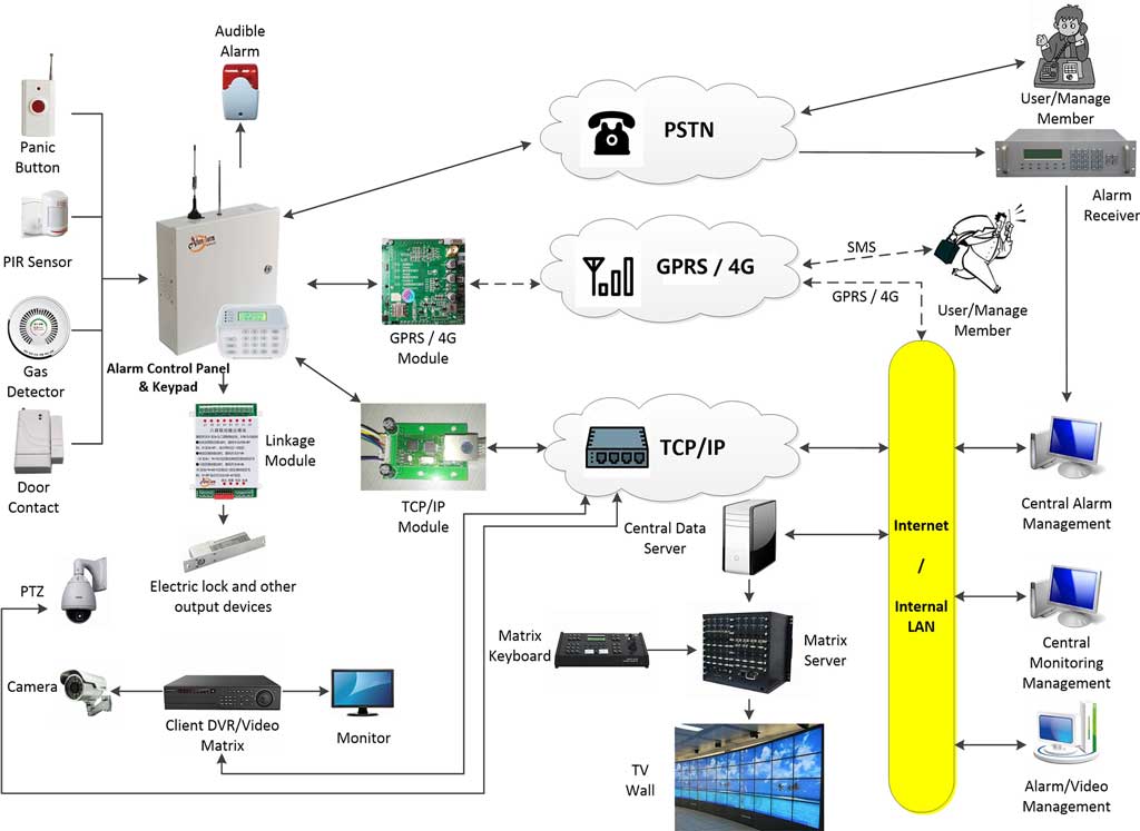
A complete, robust network alarm system for unstable environments consists of the following layers:
- Alarm Control Panel — the core processing unit (must support offline operation)
- Sensors and Detectors — PIR motion sensors, door contacts, glass break detectors, vibration sensors, smoke detectors, gas detectors, panic buttons
- Local Storage Module — embedded in the panel, stores events in non-volatile memory
- Communication Modules — TCP/IP Ethernet + 4G/LTE (dual path, with automatic failover)
- Siren and Output Devices — audible and visual alarms triggered locally
- Cloud Platform / Alarm Monitoring Center — receives events, manages user accounts, dispatches response (optional but strongly recommended)
- Mobile App / Monitoring Center Client — for user self-monitoring and remote arm/disarm
All seven layers must function. In unstable environments, the system must remain operational even when Layer 6 is temporarily unreachable.
3.2 Step 1: Selecting the Right Alarm Panel
The control panel is the most important hardware decision. A weak panel will undermine every other design choice. When evaluating panels for deployment in unstable network environments, verify the following:
Mandatory panel requirements:
- Supports dual communication modules simultaneously (Ethernet + 4G) with automatic failover
- Has built-in local event storage (minimum 1,000 events in non-volatile memory)
- Can execute all security logic locally without cloud dependency
- Supports OTA (over-the-air) firmware upgrades for remote maintenance
- Has a real-time clock that maintains accurate timestamps during network outages
- Supports multiple alarm reporting paths (IP + 4G + SMS)
- Built-in tamper detection (panel housing and communication lines)
Pre-purchase checklist — ask your supplier these questions:
- Does the panel trigger the siren if the internet has been down for 24 hours?
- Does it queue and retransmit events after reconnection?
- Does it support simultaneous Ethernet and 4G reporting?
- What is the maximum local event log capacity?
- What happens to stored events if power is lost? (Answer must be: they are retained in non-volatile memory)
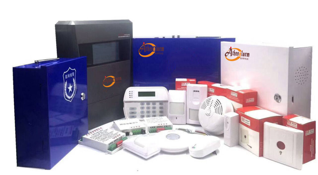
Recommended panel series for this use case: Panels such as the Athenalarm AS-9000 series, which support both TCP/IP and 4G communication modules with local storage and offline execution, represent the type of architecture required for these deployments.
3.3 Step 2: Designing Dual Communication Channels
Primary Channel: TCP/IP (Ethernet or WiFi)
Advantages:
- Low cost per data unit
- High bandwidth for video-linked alarm verification
- Stable when the local ISP is working
Weaknesses:
- Dependent on ISP infrastructure
- Fails during power cuts affecting routers
- Single point of failure if no 4G backup exists
Configuration steps:
- Assign a static IP to the panel, or use a reliable DDNS service
- Configure the panel to report to the alarm monitoring center server via TCP
- Set heartbeat interval to 30–60 seconds to detect connection drops quickly
- Enable ACK-based reporting (the server must acknowledge each event)
Backup Channel: 4G/LTE Cellular
Advantages:
- Completely independent of the local ISP
- Highly reliable in urban and peri-urban environments
- Enables reporting even during physical line cuts (common in burglaries)
Weaknesses:
- Monthly data cost
- Coverage gaps in rural or remote areas
- SIM card management required at scale
Implementation tips:
- Use industrial-grade SIM modules, not consumer-grade USB dongles
- Where possible, use multi-carrier SIM cards to increase coverage
- Enable automatic APN configuration for the target market
- Set a data budget alert if the 4G module is used as backup only
Failover Logic (Critical — Configure This Carefully)
The failover sequence must be automatic, fast, and transparent. The typical field-standard configuration is:
- Panel continuously sends heartbeats to monitoring center via TCP/IP (every 30–60 seconds)
- If three consecutive heartbeats are missed → declare TCP/IP failure
- Panel automatically activates 4G module and begins reporting via cellular
- All queued events (stored locally during the gap) are retransmitted in priority order
- TCP/IP connection is continuously monitored in the background
- When TCP/IP reconnects and is confirmed stable → automatically switch back to primary
Critical: The switch from TCP/IP to 4G must happen within 60–90 seconds maximum. Longer failover gaps result in missed alarms if an intrusion occurs during the transition window.
3.4 Step 3: Implementing Local Event Caching
When offline, every event that occurs must be captured and stored. This is not optional.
Recommended storage architecture:
- Use circular buffer with priority override
- Buffer is organized by priority tier:
- Priority 1 (Never delete first): Intrusion alarm, fire alarm, panic button, hold-up alarm
- Priority 2: Tamper alarm, communication failure alarm
- Priority 3: Arm/disarm events, low battery, zone bypass
- When buffer is full, lowest-priority events are overwritten first
- All stored events include: timestamp, zone number, event type, panel ID, arm state
Configuration steps:
- Enable local event logging in the panel configuration software
- Set buffer capacity to maximum (typically 1,000–10,000 events depending on panel)
- Configure priority levels per event type
- Enable “store-and-forward” mode: panel queues all events when offline and uploads in batch when connectivity resumes
- Verify in the panel’s log that events recorded during a simulated outage appear correctly after reconnection
3.5 Step 4: Building Reliable Data Transmission Logic
A strong network alarm system does not just send data — it confirms delivery. Unconfirmed transmission is the same as no transmission in high-stakes security environments.
Key strategies:
- ACK (acknowledgment) mechanism: The monitoring center server must send an acknowledgment for every received event. If no ACK is received within a defined timeout, the panel retransmits.
- Event ID tracking: Every event is assigned a unique sequential ID. The server uses this ID to detect duplicates and gaps.
- Retry until confirmed received: The panel must not delete a stored event until it receives a confirmed ACK from the server.
- Duplicate detection at the server: The monitoring center software must deduplicate retransmitted events to avoid false multiple-alarm records.
Protocol consideration: For unstable networks, use binary-based proprietary protocols (like the Contact ID protocol or SIA DC-09) rather than HTTP/JSON. Binary protocols are more compact, more resilient to partial packet loss, and better suited to low-bandwidth environments.
3.6 Step 5: Local Alarm Execution in Offline Mode
When the panel is completely disconnected from the internet, the following must still function without any cloud dependency:
Must function offline:
- Siren/strobe triggering — based on locally stored zone rules
- Entry and exit delays — panel timer-based, no cloud required
- Keypad arm/disarm — PIN code verification stored locally on the panel
- Zone bypass — user-configurable locally
- Output relay triggering — for linked devices (lights, locks, gates)
Optional offline alert methods:
- Bluetooth notification — some panels can push local alerts to a user’s phone via Bluetooth when on-site
- LAN-based push notification — if the local network is still up even when internet is down, the panel can send alerts to devices on the same LAN segment
- Voice dialer — panel calls pre-programmed phone numbers directly via 4G voice call, not data, to notify the user
Configuration steps for offline mode:
- Program all zones (zone type, entry delay, exit delay) directly into the panel — do not rely on cloud-stored rules
- Store user PIN codes and access levels in panel non-volatile memory
- Test keypad arm/disarm with network cable physically unplugged
- Test siren triggering with both network cable and 4G SIM removed
- Confirm that the panel log records events correctly even in full offline mode
Chapter 4: Advanced Techniques for Harsh Environments
4.1 SMS as Emergency Backup Communication
Even when all data channels fail, SMS voice/text messaging typically continues to work on cellular networks. In markets where data infrastructure is unreliable but voice/SMS coverage is widespread (most of Sub-Saharan Africa and rural Southeast Asia), SMS is a critical last-resort channel.
Configure SMS alerts for:
- Intrusion alarm triggers (Zone X Alarm — Panel ID Y)
- Panel communication failure
- Mains power failure
- Panel tamper detection
- System health status (daily heartbeat SMS)
Implementation notes:
- Pre-program up to 5–10 phone numbers in the panel for SMS notification
- Use SMS for alert delivery only, not for arm/disarm commands (security risk unless properly encrypted)
- Verify local SMS delivery reliability for the target SIM carrier before deployment
- Some panels support two-way SMS: the user can reply with a command to request a status update
4.2 Power Backup Integration
Network instability in developing markets is almost always correlated with power instability. A system that handles network failure perfectly but loses power has accomplished nothing.
Power backup requirements by installation type:
| Installation Type | Minimum Battery Backup |
|---|---|
| Residential | 8 hours |
| Small commercial | 12 hours |
| Bank branch / high-security | 24 hours |
| Unattended remote site | 48–72 hours (solar + battery) |
Additional power recommendations:
- Install a UPS (Uninterruptible Power Supply) on the router, modem, and network switch — not just on the alarm panel
- Use a UPS with at least 2–4 hours of router runtime (prevents network loss during brief power cuts)
- For remote sites with frequent long outages, consider a solar charging system with deep-cycle battery backup
- Panel battery health must be monitored and reported — a dead backup battery provides zero protection
4.3 Data Compression and Protocol Optimization
In weak or throttled networks, reducing the size of transmitted data directly reduces transmission failure rates.
Practical optimizations:
- Use binary alarm protocols (Contact ID, SIA DC-09) instead of verbose HTTP/JSON APIs
- Batch non-critical events (low battery, arm/disarm logs) and upload them in a single compressed packet when connectivity is good
- Transmit alarm events only over 4G — reserve higher-bandwidth reporting for the primary TCP/IP channel
- Avoid sending video thumbnails or images over 4G unless the connection is confirmed stable and fast
Result: Binary protocols typically reduce payload size by 60–80% compared to JSON/HTTP, dramatically improving transmission success rates under poor network conditions.
4.4 Store-and-Forward Mechanism (Detailed Implementation)
The store-and-forward pattern is the single most important architectural decision for offline resilience. It works as follows:
Offline phase:
- All events are written to local non-volatile storage with timestamp, priority, and status = “pending”
- The panel continues to monitor for connectivity restoration
- Local alarm functions (sirens, outputs, displays) operate normally
Reconnection phase:
- Panel detects connectivity (TCP/IP or 4G) is restored
- Panel initiates a reconnection handshake with the monitoring center server
- Panel transmits stored events in priority order, starting from the oldest highest-priority event
- For each event, the server sends ACK; the panel marks the event as “delivered”
- Once all pending events are delivered, the panel resumes normal real-time reporting
- The monitoring center displays the historical events with their original timestamps, clearly marked as “delayed delivery”
What to verify during testing:
- Simulate a 6-hour outage → reconnect → confirm all events appear in the monitoring center with correct timestamps
- Simulate a full memory buffer scenario (generate more events than buffer capacity) → confirm that priority-1 events are never lost
4.5 Watchdog Timer and Self-Recovery
In long-term unattended deployments (common in Africa and remote Asia-Pacific sites), the panel must be able to recover from software freezes or communication stack failures without human intervention.
Recommended self-recovery features:
- Hardware watchdog timer that reboots the panel if firmware becomes unresponsive
- Automatic reconnection logic that restarts the communication module after a defined number of failed attempts
- Daily self-test report transmitted to the monitoring center (confirms panel is alive and operational)
- Remote reboot capability via the 4G channel (operator can reboot the panel without a site visit)
Chapter 5: Sensor Selection for Harsh Environments
The quality of the sensor layer is just as important as the communication architecture. In hot, humid, dusty, and electrically noisy environments — common across Africa and Southeast Asia — standard sensors may fail prematurely or generate excessive false alarms.
5.1 Environmental Considerations for Sensor Selection
| Environment Factor | Impact on Sensors | Recommended Solution |
|---|---|---|
| High humidity (>80% RH) | Corrosion, condensation inside detectors | IP54-rated or better sensors; sealed housings |
| Extreme heat (>40°C) | PIR sensitivity drift; shortened battery life | Temperature-compensated PIR sensors |
| Insects and rodents | False triggers on PIR sensors | Dual-technology PIR/microwave sensors |
| Electrical noise | False triggers on vibration detectors | Digital vibration detectors with adjustable sensitivity |
| Dusty environments | Photoelectric smoke detector contamination | More frequent sensor maintenance schedule |
5.2 Recommended Sensor Types for Unstable Environments
For intrusion detection:
- Dual-technology PIR/microwave detectors — significantly reduce false alarms in environments with insects, temperature fluctuations, and air movement
- Door contacts — the most reliable detector type; use heavy-duty versions for metal doors
- Digital vibration detectors — for safes, ATM machines, and metal shutters; use models with adjustable sensitivity
- Glass break detectors — for retail environments; verify the acoustic frequency range matches local glass types
For emergency notification:
- Wireless panic buttons — for staff in stores, banks, and hospitality environments; choose models with long battery life and low-latency RF communication
- Hold-up alarm buttons — discreet, foot-operated or hand-operated, wired directly to the panel
For environmental monitoring:
- Photoelectric smoke detectors — more resistant to dust-related false alarms than ionization type
- Gas detectors — for kitchens, generator rooms, and fuel storage areas
5.3 Wired vs. Wireless Sensors in Unstable Environments
In high-EMI environments (near generators, industrial equipment, or poorly regulated electrical infrastructure), wired sensors on a RS-485 bus are more reliable than wireless sensors operating on 433MHz or 868MHz RF bands.
Wireless sensors are preferable when:
- Cable installation is impractical (retrofits, rented premises)
- The installation needs to be completed quickly
- The environment is electrically clean
Hybrid approach (recommended for most commercial deployments):
- Wired sensors on the RS-485 bus for permanent, high-value zones
- Wireless sensors for supplementary coverage zones and temporary installations
Chapter 6: Deployment Strategy for Africa and Southeast Asia
6.1 Environment-Specific Challenges
| Factor | Impact | Recommended Solution |
|---|---|---|
| Poor ISP infrastructure | Frequent disconnections | Dual-channel (TCP/IP + 4G) mandatory |
| High mobile data cost | Requires bandwidth optimization | Binary protocols; batch uploading; 4G for alarms only |
| Limited local technical support | Needs simple installation and remote management | OTA firmware; remote diagnostics; clear documentation |
| Power instability | System goes offline with grid | UPS for panel and router; battery backup 12–24 hours |
| High ambient temperature | Hardware reliability issues | Industrial-grade components; ventilated enclosures |
| Regulatory requirements | Local compliance may be required | Verify local alarm system regulations before deployment |
6.2 Recommended Deployment Model
Best practice architecture stack for Africa / Southeast Asia:
- Communication: Dual-path (TCP/IP primary + 4G backup) with SMS fallback
- Processing: Local-first (edge intelligence on panel)
- Storage: Non-volatile local event buffer (1,000+ events)
- Monitoring: Cloud-assisted monitoring center with mobile app access
- Power: Panel + router UPS; minimum 12-hour battery backup
- Sensors: Dual-technology detectors in hot/humid zones; wired RS-485 bus preferred for commercial deployments
6.3 Installation Best Practices (Step-by-Step)
Step 1: Site survey
- Map all entry points, high-value areas, and sensor placement positions
- Test 4G signal strength at the planned panel location (use a mobile phone as a test device)
- Identify the nearest power source and UPS placement position
- Check for sources of electrical interference (generators, welding equipment, HVAC units)
Step 2: Panel and communication module installation
- Mount the panel in a locked, ventilated enclosure away from direct sunlight and moisture
- Install the external 4G antenna on the roof or exterior wall for maximum signal gain
- Route the Ethernet cable to the router — use Cat6 cable for reliability
- Insert the SIM card and confirm 4G registration before proceeding
Step 3: Sensor wiring and placement
- For wired sensors: run cables through conduit to protect against insects, moisture, and tampering
- For PIR sensors: mount at 2.0–2.4 meters height, angled toward the most likely intrusion path
- For door contacts: mount the magnet on the door and the reed switch on the frame, gap must be less than 5mm when closed
- For glass break detectors: mount within 6 meters of the target glass surface on a wall or ceiling
Step 4: Panel programming
- Program all zones directly into the panel (zone type, entry delay, exit delay, alarm delay)
- Store user PIN codes in panel memory
- Configure all reporting paths: TCP/IP server IP/port, 4G APN settings, SMS recipient numbers
- Set heartbeat interval to 30–60 seconds
- Enable store-and-forward mode and set event buffer to maximum capacity
Step 5: Communication testing
- With Ethernet connected and 4G active: trigger a test alarm → confirm receipt at monitoring center via TCP/IP
- Disconnect Ethernet cable → trigger a test alarm → confirm failover to 4G within 90 seconds → confirm receipt at monitoring center via 4G
- Remove SIM card → trigger a test alarm → confirm SMS delivery to programmed phone numbers
- Reconnect Ethernet → confirm automatic fallback to TCP/IP primary channel
Step 6: Offline mode testing
- Disconnect both Ethernet cable and remove SIM card
- Trigger multiple test alarms in different zones
- Confirm that: siren sounds, strobe activates, keypad displays alarm, events are logged locally
- Reconnect Ethernet → confirm all stored events upload to monitoring center with correct timestamps
Step 7: Final handover
- Document panel IP address, SIM number, APN settings, and firmware version
- Provide the end user with instructions for local arm/disarm and emergency PIN override
- Set up a maintenance schedule (battery test every 6 months; sensor sensitivity test every 12 months)
- Register the installation in the monitoring center platform with full site details

Chapter 7: Testing and Validation (Critical — Most Deployments Skip This)
Inadequate testing before handover is the leading cause of field failures. In unstable network environments, standard “power-on and see if it works” testing is completely insufficient.
7.1 Simulate Real Conditions Before Deployment
Before handing over any installation to a customer:
- Disconnect the internet completely for at least 30 minutes → trigger alarms → verify local operation and event storage
- Introduce artificial packet loss using a router’s QoS/traffic shaping settings (set 20–30% random packet loss) → verify alarm delivery success rate
- Simulate high latency (add 500ms delay artificially) → verify the panel handles timeout gracefully without dropping events
- Simulate a power failure (cut mains power) → verify battery backup activates immediately → verify panel continues operating → restore power and verify panel reconnects
7.2 Required Test Scenarios
Every installation must pass all of the following scenarios before handover:
| Test Scenario | Pass Criterion |
|---|---|
| Intrusion during full internet outage | Siren triggers, event logged locally |
| Recovery after 1-hour outage | All stored events upload with correct timestamps |
| Event synchronization | No duplicate or missing events at monitoring center |
| TCP/IP to 4G failover | Failover completes within 90 seconds |
| 4G to SMS fallback | SMS alert received within 60 seconds of 4G failure |
| Power failure with battery backup | Panel operates continuously; events logged correctly |
| Mains restored after battery | Panel reconnects and resumes reporting within 60 seconds |
| Tamper detection | Tamper event sent via available channel immediately |
7.3 KPI Metrics — Define These Before Deployment
Establish clear performance benchmarks:
- Alarm delivery success rate: Target ≥ 99% across all channels combined
- Failover switching time (TCP/IP to 4G): Target ≤ 90 seconds
- Event data recovery completeness after outage: Target 100% (zero events lost)
- False alarm rate: Target < 1 per zone per month
- Battery backup runtime: Must meet specified minimum for installation type
If a system does not meet these benchmarks during pre-handover testing, it must not be handed over. Fixing it in the office takes hours. Fixing it after a missed intrusion alarm takes years of reputation repair.
Chapter 8: Common Mistakes and How to Avoid Them
These are the mistakes that experienced installers still make when entering new markets with unstable infrastructure. Each one has caused real-world security failures.
Mistake 1: Cloud-Only Design
What happens: The panel reports exclusively to a cloud server. When internet fails, no events are transmitted. When connectivity is restored, events are permanently lost.
Fix: Every panel must store events locally and retransmit after reconnection. Non-negotiable.
Mistake 2: Single Communication Channel
What happens: TCP/IP is the only reporting path. A cut cable, ISP outage, or router power failure creates a total communication blackout.
Fix: Implement dual-path at minimum (TCP/IP + 4G). Never deploy with a single channel in an unstable environment.
Mistake 3: No Local Event Storage
What happens: Events generated during an outage are held in RAM. When power is cut (as frequently happens in these markets), all buffered events are erased.
Fix: Store events in non-volatile memory (flash/EEPROM). RAM-based buffering is not acceptable for professional security deployments.
Mistake 4: Ignoring Power Backup for Network Equipment
What happens: The alarm panel has a battery backup, but the router and modem do not. Power cut → router goes offline → TCP/IP path fails → 4G failover must carry all traffic. If 4G is also unavailable, the system goes fully offline.
Fix: Install UPS for the router, modem, and any network switch. This is one of the most commonly overlooked steps in field deployments.
Mistake 5: Insufficient Pre-Handover Testing
What happens: The system is tested only under normal conditions. First real-world outage reveals failures that were entirely predictable.
Fix: Run every scenario in the test table above before handover. Budget 2–4 hours for testing per installation. It is far cheaper than a callback.
Mistake 6: Using Consumer-Grade SIM Modules
What happens: Consumer-grade USB dongles or cheap SIM modules overheat, fail under sustained use, and lose connectivity randomly.
Fix: Use industrial-grade embedded SIM modules rated for continuous operation in high-temperature environments. The cost difference is negligible compared to the reliability gain.
Mistake 7: Hardcoding a Single Reporting Server IP
What happens: The monitoring center changes its IP address or migrates to a new server. All panels in the field stop reporting.
Fix: Use a domain name (FQDN) for the reporting server address rather than a static IP. The panel resolves the domain name at each connection attempt, allowing transparent server migration.
Chapter 9: Integration with Alarm Monitoring Centers
A network alarm system does not operate in isolation. It must integrate effectively with a central monitoring center — whether that is a professional alarm receiving center (ARC), an in-house security operations center, or a cloud-based monitoring platform.
9.1 What the Monitoring Center Must Receive
For each alarm event, the monitoring center platform must receive and display:
- Panel ID (unique identifier for the installation)
- Site name and address (pre-registered in the platform)
- Zone number and zone name (e.g., Zone 3 — Rear Door)
- Event type (intrusion, tamper, power failure, arm, disarm, etc.)
- Timestamp (original event time, not receipt time — critical for offline events)
- Communication path used (TCP/IP or 4G — for diagnostic purposes)
- Delivery status (real-time or delayed — flag events delivered after an outage)
9.2 Video Verification Integration
For higher-security deployments (banks, ATM sites, jewelry stores), the network alarm system should be integrated with CCTV to enable video-verified alarm response.
When an intrusion alarm triggers:
- The alarm monitoring center software automatically retrieves the live or pre-alarm video clip from the nearest camera
- The operator views the video within 30–60 seconds of alarm receipt
- Verified intrusion → immediate dispatch of security response
- No confirmed intrusion → event logged as unverified, no unnecessary dispatch
This integration dramatically reduces false alarm dispatch costs — a major issue in markets where police response to unverified alarms is slow or unreliable.
Technical requirement: The alarm panel’s reporting software must be able to trigger a camera snapshot or video clip pull from compatible CCTV systems (such as Hikvision, Dahua, or XM) at the moment of alarm.
9.3 Remote Arm/Disarm and System Management
A properly designed network alarm system enables the monitoring center operator (or end user via mobile app) to:
- Remotely arm or disarm the panel over the internet or 4G
- Check real-time zone status (open/closed/alarmed)
- Bypass specific zones temporarily without attending the site
- Trigger a remote siren test to verify output functionality
- Download the panel event log for audit purposes
All remote commands must be authenticated and encrypted. Remote arm/disarm commands transmitted in plaintext are a security vulnerability.
Chapter 10: Commercial Value for Buyers and Distributors
For bulk buyers, regional distributors, and system integrators, a robust network alarm system designed for unstable environments is not just a technical advantage — it is a significant market differentiator that directly affects revenue and customer retention.
10.1 Why It Sells Better in Emerging Markets
Customers in Africa, Southeast Asia, and Latin America have experienced too many “smart” alarm systems that failed at the worst moments. They are not buying features — they are buying proven reliability under local conditions.
When you can demonstrate that your system:
- Kept recording during a 4-hour power cut
- Delivered the intrusion alarm via 4G when the internet was down
- Uploaded all stored events when connectivity was restored
…you are not selling a product. You are selling proof of performance. That is a fundamentally different and far more compelling commercial proposition.
10.2 Quantifiable Business Benefits for the Integrator
- Fewer callback service visits — systems designed for offline resilience fail less frequently
- Lower warranty claim rates — most warranty claims in unstable environments come from communication failures, which are eliminated by dual-path design
- Higher customer retention — customers who experience zero missed alarms do not switch providers
- Faster installation approvals — monitoring centers are more willing to accept panels with proven offline capability
- Premium pricing justification — a demonstrably more reliable system commands a higher price per unit and per monitoring contract
10.3 Competitive Positioning
In markets where the dominant competition is low-cost, single-channel, cloud-dependent systems, a dual-path, offline-capable network alarm system occupies a completely different position:
You are not selling “an alarm system.”
You are selling: “A security system that works even when everything else fails.”
That message resonates immediately with buyers who have experienced real network and power outages. It closes deals that specification sheets cannot.
Chapter 11: Future Trends in Network Alarm Technology for Unstable Environments
The evolution of communication technology is opening new possibilities for alarm systems deployed in challenging environments. The following trends are already emerging and will become commercially significant over the next three to five years.
11.1 Multi-SIM and eSIM Automatic Carrier Switching
Rather than relying on a single SIM card from a single carrier, next-generation 4G alarm modules will support automatic switching between multiple carriers based on real-time signal quality. This is particularly valuable in markets where no single carrier has comprehensive national coverage.
11.2 Satellite Backup Communication
With the global expansion of low-earth orbit (LEO) satellite networks (including Starlink and similar services), satellite connectivity is becoming a viable emergency backup channel for remote alarm installations. While currently too expensive for standard deployments, satellite backup modules will become cost-accessible for high-value remote sites (mining operations, remote substations, agricultural facilities) within the next few years.
11.3 Edge AI for False Alarm Reduction
AI-based decision-making running directly on the alarm panel (not in the cloud) will become standard. Edge AI can distinguish between a genuine intrusion event and a false trigger caused by insects, small animals, or environmental changes — without requiring any internet connectivity to make that determination.
11.4 Predictive Communication Channel Management
Future alarm panels will analyze historical connectivity data (which channel fails at what time, how long outages typically last) and proactively pre-buffer events before predicted outage windows, further reducing event loss risk.
11.5 Blockchain-Based Alarm Event Integrity
For high-security applications (banks, critical infrastructure), blockchain-based event logging provides tamper-proof audit trails. Each alarm event is cryptographically signed and recorded in a distributed ledger, making it impossible to retrospectively alter or delete the alarm history.
Conclusion: Reliability Is the Real Intelligence
A truly intelligent network alarm system is not defined by how it performs under perfect conditions — but by how it behaves when everything goes wrong.
If your system can:
- Operate fully offline — detecting, alerting, and logging without internet
- Store every event — in non-volatile memory, with accurate timestamps
- Switch seamlessly between communication channels — from TCP/IP to 4G to SMS, automatically
- Recover data without loss — uploading stored events in priority order when connectivity resumes
- Maintain local alarm execution — triggering sirens, outputs, and local notifications independent of the cloud
…then you have built something far more valuable than a “smart” device.
You have built a trusted security infrastructure — one that earns its place in the harshest environments on earth.
Final Thought: For Decision Makers in Emerging Markets
If your target markets include Africa, Southeast Asia, or any region with unstable connectivity, then designing for resilience is not optional — it is mission-critical.
The most expensive alarm system is not the one with the highest price tag. It is the one that stays silent during a real intrusion because the internet went down twenty minutes earlier.
In this market, the systems that survive poor networks are the ones that win — and the integrators who deploy them are the ones who build lasting businesses.
If you are evaluating or sourcing a reliable network alarm system designed for real-world performance in unstable internet environments, prioritize field-proven resilience over specification-sheet features. Request demonstration of offline mode, failover switching, and store-and-forward event recovery before making any procurement decision. The difference between a system that passes a showroom demo and one that performs in the field defines the outcome of every deployment.