
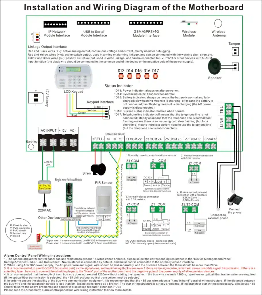
Proper Burglar Alarm control panel wiring is the foundation of any reliable intrusion detection system. For installers, product managers, and procurement decision-makers, the wiring quality of the alarm control panel directly affects system stability, false alarm rates, long-term maintenance costs, and even compliance with industry standards. Whether you are deploying systems in residential, commercial, or enterprise environments, understanding correct alarm panel wiring practices is essential for ensuring secure and scalable installations.
This guide consolidates field-proven techniques, authoritative standards, and practical troubleshooting insights to help you achieve professional-grade results in burglar alarm system wiring.
Introduction
Incorrect or inconsistent wiring remains one of the most common causes of false alarms, zone failures, device malfunctions, and communication instability in intrusion alarm systems. Many system failures—especially in large sites with multiple panels or expansion modules—are directly tied to wiring mistakes such as improper grounding, incorrect resistor placement, or unsuitable cable routing.
This article provides a comprehensive, practical guide for wiring a burglar alarm control panel, offering technical clarity for installers and valuable evaluation insights for product managers and bulk procurement decision-makers. You will learn the essential wiring principles, step-by-step installation procedures, key precautions, and troubleshooting approaches that align with industry standards such as UL 681 and NFPA 70.
1. Understanding Burglar Alarm Control Panel Basics
A burglar alarm control panel functions as the central processing unit of the intrusion detection system. All sensors, keypads, power supplies, sirens, and communication modules are wired into the control panel, making proper alarm panel wiring crucial for stable system performance.
Key Components Involved in Alarm Panel Wiring
- Zones / Inputs: Support motion detectors, door contacts, glass-break sensors, shock sensors, etc.
- Auxiliary Power Output (AUX): Typically 12V DC, used to power detectors and modules.
- Bell Output: Drives external sirens or sounders.
- Keypad Bus: Communication line between the keypad and control panel.
- Communication Modules: PSTN, GSM, 4G/5G, Ethernet/IP for remote monitoring.
- Backup Battery: Ensures system operation during power failures.
Understanding these components helps installers plan the wiring path and enables procurement decision-makers to evaluate system scalability and compatibility.
Wiring Fundamentals
- Cable Types:
- 4-core or 6-core twisted pair for keypads
- 2-core or 4-core cables for sensors
- Shielded cables for high-interference environments
- Voltage Requirements:
Most systems use 12V DC, but always follow manufacturer specifications. - End-of-line (EOL) Resistive Supervision:
Mandatory for tamper detection and fault reporting. UL 681 recommends supervised circuits for all perimeter zones.
Professionals must consider both wiring simplicity and future scalability, particularly when deploying large burglar alarm systems that may require zone expansion modules or integration with third-party sensors.
2. Preparing for Burglar Alarm Control Panel Wiring
Proper preparation significantly reduces wiring errors and system downtime.
Tools and Materials
- Wire strippers, crimp connectors
- Multimeter for voltage and resistance checks
- Ferrules and terminal blocks
- Labelled cables (color-coded when possible)
- Cable ties and protective conduits
- Screwdrivers and insulation tape
Product managers and procurement teams should standardize these items to ensure consistent installation quality across multiple deployment sites.
Site Assessment Essentials
Before wiring begins:
- Identify optimal panel location—central, well-ventilated, and secure.
- Evaluate cable routing paths to avoid power lines or high-EMI zones.
- Ensure proper power source availability and grounding points.
- Assess special environmental conditions (moisture, vibration, metal structures).
Safety and Compliance
Follow relevant regulations:
- NFPA 70 (National Electrical Code): Electrical safety requirements
- UL 681: Installation requirements for burglar and holdup alarm systems
- Ensure circuits are isolated before wiring to avoid accidental short circuits
- Use proper grounding to eliminate noise and reduce false alarms
3. Step-by-Step Guide to Wiring a Burglar Alarm Control Panel
This procedure applies to most major alarm systems (e.g., Honeywell, DSC, Paradox, Texecom, Bosch).
Step 1: Power Off the System
Never wire the panel while it is powered. Disconnect AC and battery.
Step 2: Mount the Panel and Prepare Cable Entry
Secure the metal box to a stable surface. Use rubber grommets for cable protection.
Step 3: Wire the Power Supply
- Connect AC transformer leads to the AC terminals.
- Connect the battery (observe polarity).
- Verify 13.8V DC charging voltage using a multimeter.
Step 4: Wire Detection Zones
For each zone:
- Connect sensor outputs to ZONE + COM.
- Install EOL resistors according to the panel’s wiring diagram (e.g., 2.2K, 4.7K, 5.6K).
- Follow the manufacturer’s recommended wiring mode:
- NO/EOL, NC/EOL, or Double EOL.
- Ensure polarity is correct for powered sensors (PIR, glass-break, shock).
Step 5: Wire the Keypad
- Connect terminals (e.g., +12V, GND, DATA, CLK).
- Avoid long unshielded runs to prevent communication noise.
Step 6: Wire the Siren Output
- Connect BELL + and BELL – to the siren.
- Add backup siren battery if required.
- Confirm current draw does not exceed the panel’s limit.
Step 7: Wire Communication Modules
- PSTN: TIP/RING
- GSM: Plug-in module + 12V power + antenna
- IP Module: Ethernet + bus connection
Proper communication wiring reduces risks of signal loss and monitoring failures.
Step 8: Power On and Program
After verifying all wiring:
- Connect the battery
- Power on AC
- Perform system programming and zone testing
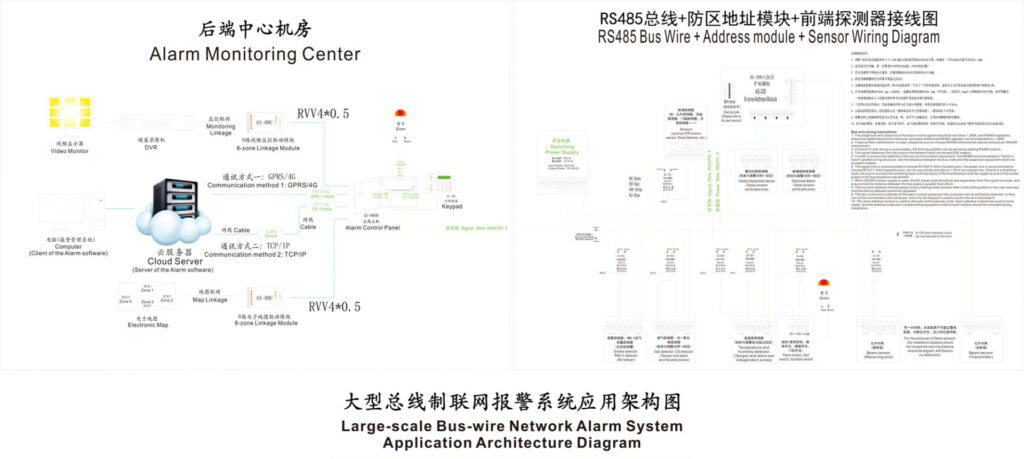
4. Key Precautions and Best Practices for Alarm Panel Wiring
Avoid Common Mistakes
- Using incorrect resistor values → Causes false alarms or open-zone faults
- Mixing cable types → Leads to inconsistent loop resistance
- Poor grounding → Causes interference and intermittent faults
- Overloading AUX output → May damage power supply circuits
Cable Management Practices
- Separate low-voltage alarm wires from AC mains
- Use trunking or conduits in commercial environments
- Label every wire to simplify maintenance
- Document all wiring paths and zone assignments
Scalability Considerations for Procurement Teams
High-quality wiring practices allow:
- Easier deployment of expansion modules
- Lower false alarm rates
- Improved maintenance efficiency in multi-site rollouts
- Higher ROI on enterprise-scale alarm systems
Reports from the Electronic Security Association (ESA) indicate that over 60% of alarm system failures are caused by wiring issues—reinforcing the need for proper installation procedures.
5. Troubleshooting Common Wiring Problems
Zone Faults or Constant Alarms
- Check EOL resistor placement
- Measure loop resistance; compare with manufacturer tolerances
- Inspect for loose terminals or corroded wires
Keypad Communication Failure
- Verify DATA and CLK connections
- Measure voltage (must be 12V DC)
- Replace damaged cables or shorten excessively long runs
Siren Not Activating
- Check BELL output voltage
- Verify current draw vs. panel rating
- Test siren backup battery
Communication Module Issues
- For GSM/IP modules:
- Check signal strength
- Verify wiring polarity
- Ensure proper SIM activation / IP settings
Power Problems
- Test transformer output
- Test battery voltage under load
- Check for blown fuses or panel overloads
Real-world case studies consistently show that structured diagnostics and proper wiring documentation reduce maintenance times by up to 40%.
Conclusion
Accurate and compliant Burglar Alarm control panel wiring is fundamental to achieving a stable, secure, and long-lasting intrusion detection system. Following the recommended steps, precautions, and industry standards ensures optimal system performance, reduces false alarm rates, and enhances reliability—whether for a single installation or large-scale enterprise deployment.
By adopting these practices, technical personnel improve installation quality, and procurement teams make better-informed decisions when selecting burglar alarm systems and accessories.
References
- Athenalarm AS-9000 Series Alarm Control Panel Wiring Instructions
- UL 681 – Installation and Classification of Burglar and Holdup Alarm Systems
Underwriters Laboratories. Industry standard for intrusion alarm installation. - NFPA 70 – National Electrical Code (NEC)
National Fire Protection Association. Electrical safety guidelines for low-voltage installations. - Electronic Security Association (ESA) Installation Guidelines
Recommended practices for professional alarm installation and wiring. - Honeywell Home / Resideo Technical Wiring Manuals
Official manufacturer documentation for control panel wiring standards. - ASIS International: Security System Reliability Study
Research report analyzing failure causes in electronic security systems. - Security Industry Association (SIA): Best Practices for Alarm Wiring
Industry whitepaper covering wiring techniques and system design principles.