
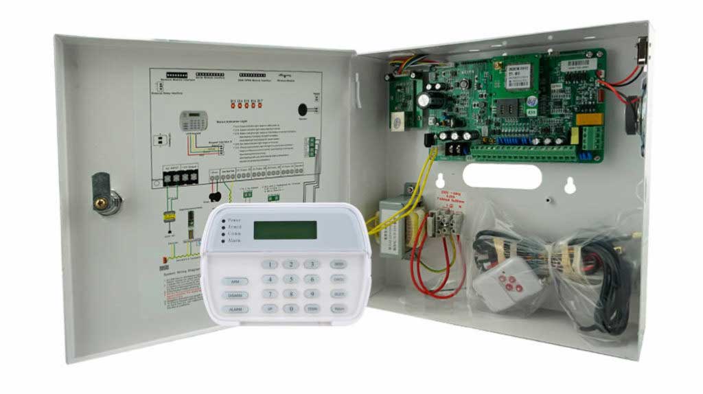
In modern intrusion detection systems, alarm resistor decoding is a foundational concept that directly affects system reliability, false alarm prevention, and fault detection accuracy. Yet many technicians still encounter misinterpreted zones, unstable supervision states, or unexplained trouble signals—often caused by improper EOL resistor interpretation rather than faulty hardware.
This guide explains how alarm panels interpret resistive values, why those values matter electrically, and how technicians can correctly design, test, and troubleshoot supervised zones in real-world installations. The focus is practical, field-oriented, and aligned with industry standards used in professional burglar alarm systems.
Why Alarm Panels Use Resistive Supervision
Modern alarm panels do not simply detect “open” or “closed” circuits. Instead, they continuously measure electrical resistance to determine the exact condition of a zone.
This approach allows panels to distinguish between:
- Normal (secure)
- Alarm (zone violated)
- Trouble (wire cut, short, or tamper)
The key component enabling this logic is the End-of-Line (EOL) resistor, installed at the far end of the zone wiring.
Without proper resistive supervision:
- A cut wire may appear normal
- Tampering can go undetected
- System integrity is compromised
This is why virtually all professional-grade intrusion panels require supervised loops.
How Alarm Panels Interpret Resistive Values
Alarm panels interpret resistive values by measuring voltage drop across the zone using internal analog-to-digital conversion. Each resistance range corresponds to a specific system state.
Typical Resistance Interpretation Logic
| Circuit Condition | Typical Resistance | Panel Interpretation |
|---|---|---|
| Normal (secure) | 1kΩ – 4.7kΩ (model dependent) | Normal |
| Alarm | Open circuit (∞ Ω) | Alarm |
| Short circuit | 0–100Ω | Trouble / Tamper |
| Tamper (dual EOL) | Intermediate value | Tamper |
The exact thresholds vary by manufacturer, but the logic remains consistent.
Common industry values:
- 1kΩ – legacy systems, some DSC models
- 2.2kΩ – Honeywell / Resideo standard
- 4.7kΩ – Bosch and European systems
Always verify values in the panel’s installation manual.
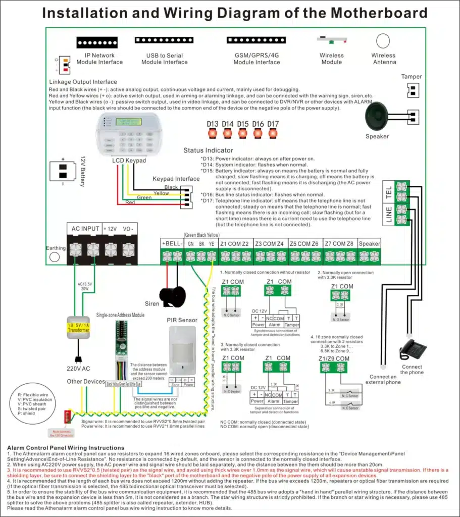
Understanding Single EOL vs Double EOL (DEOL)
Single EOL Configuration
A single resistor placed at the end of the circuit allows detection of:
- Normal
- Alarm
- Open circuit
However, tamper detection is limited.
Double EOL (DEOL) Configuration
Using two resistors enables:
- Normal
- Alarm
- Tamper
- Wire cut
- Short circuit
This is common in commercial and high-security environments.
Example (2 × 2.2kΩ configuration):
- 4.4kΩ → Normal
- 2.2kΩ → Alarm
- 0Ω → Short
- ∞ → Open
This method significantly improves intrusion detection reliability.
Step-by-Step: How to Test Alarm Resistor Interpretation
This procedure is suitable for entry-level and experienced technicians alike.
Step 1: Power Down Safely
Disconnect AC power and battery backup. Wait 20–30 seconds to discharge internal capacitors.
Step 2: Identify Zone Terminals
Locate the specific zone input (e.g., Z1 / COM). Disconnect field wiring.
Step 3: Measure Baseline Resistance
Using a digital multimeter:
- Set to resistance (Ω)
- With no resistor connected → reading should be OL (open)
Step 4: Simulate Zone Conditions
Test using known resistor values:
| Simulation | Expected Reading |
|---|---|
| Normal | Exact EOL value |
| Alarm | Infinite resistance |
| Short | Near 0Ω |
| Tamper (DEOL) | Mid-range value |
Step 5: Reconnect and Program
Reconnect field wiring and program:
- Zone type
- Supervision mode
- EOL configuration
Verify zone responses using the keypad or system diagnostics.
Step 6: Confirm via Panel Diagnostics
Many modern panels provide live resistance readings or event logs—use them to validate correct interpretation.
Common Problems and How to Fix Them
1. False Trouble Conditions
Cause: Long cable runs increasing total resistance.
Solution:
- Calculate wire resistance (approx. 0.02Ω per foot for 22 AWG).
- Adjust panel thresholds if supported.
2. Inconsistent Zone Status
Cause: Loose terminals or oxidized resistor leads.
Solution:
- Re-terminate connections
- Use sealed, flame-retardant resistors
3. Incorrect EOL Placement
Cause: Resistor installed at panel instead of end device.
Solution:
- Always place EOL at the furthest physical point of the loop.

Field Case Example: Commercial Retail Deployment
In a 2023 multi-site retail deployment reviewed by the Security Industry Association (SIA), recurring false alarms were traced to humidity-affected 4.7kΩ carbon resistors installed near storefront doors.
After replacing them with sealed 2.2kΩ metal-film resistors and relocating them to protected junction points, nuisance alarms dropped by over 40% within three months.
This case highlights how environmental conditions directly affect resistor stability and alarm reliability.
Advanced Practices for High-Reliability Systems
Experienced installers can further improve system integrity by:
- Using addressable zone expanders for precise resistance reporting
- Logging resistance trends during maintenance cycles
- Combining wired EOL supervision with wireless redundancy
- Labeling resistor values in as-built documentation
According to a 2024 UL evaluation, systems with properly documented and verified EOL supervision showed 25% fewer undetected faults compared to unsupervised or poorly configured systems.
Final Thoughts: Mastering Alarm Resistor Interpretation
Understanding how alarm panels interpret resistive values is essential for building reliable intrusion detection systems. Correct EOL resistor selection, placement, and testing dramatically reduce false alarms and undetected faults.
For technicians, mastering alarm resistor decoding is not optional—it is a core professional skill that directly impacts system credibility and customer trust.