
In today’s high-stakes security landscape, large facilities face threats that traditional standalone alarms simply cannot handle. A single break-in at an industrial park, a vandalism incident on a university campus, or unauthorized access in a sprawling warehouse can cost hundreds of thousands in losses, downtime, and liability. System integrators, security engineers, and technical decision-makers know the pain: fragmented systems that fail to scale, false alarms that waste resources, and single points of failure that leave critical assets exposed.
The solution? A properly designed network alarm system built on true multi-layer architecture. This isn’t just another intrusion detection setup—it’s an enterprise-grade network alarm infrastructure that delivers real-time detection, reliable communication, and centralized management across thousands of zones. In this ultimate practical guide, I’ll walk you through every layer, every topology choice, every redundancy decision, and every deployment nuance so you can construct a system that actually works under real-world pressure.
Whether you’re protecting a 500,000-square-foot industrial complex, a multi-building campus, a high-value warehouse, or a mixed-use commercial development, this step-by-step blueprint will give you the exact architecture, component selection criteria, and implementation tactics used by top-tier integrators worldwide. By the end, you’ll know precisely how to avoid the costly mistakes that plague 70% of large-scale projects and deliver a network alarm system that scales, survives outages, and provides verifiable protection your clients can trust.
Why Large Facilities Demand a Networked Multi-Layer Approach
Traditional wired alarm panels worked fine for small buildings, but they collapse under the demands of modern facilities. Cabling runs become prohibitively expensive, maintenance windows shrink, and centralized oversight disappears. A true network alarm system changes everything by leveraging IP connectivity, cloud intelligence, and layered defense—while seamlessly integrating with video surveillance systems for automatic real-time video pop-ups upon any intrusion trigger.
The core philosophy is defense-in-depth translated into three explicit layers:
- Detection Layer – Where threats are first identified.
- Communication Layer – Where signals travel reliably and redundantly.
- Management Layer – Where decisions are made and responses coordinated.
This isn’t theoretical. It’s the architecture that lets a single operations center monitor 50 buildings across 10 square kilometers with sub-second alarm verification and automatic video pop-up linkage. It supports pre-prevention through robust perimeter protection, immediate handling via automated alerts and police forwarding, and post-event retrospective analysis with recorded video evidence. Let’s break it down component by component.
Core Components of a Professional Network Alarm System
1. IP-Enabled Alarm Panels – The Intelligent Heart of Every Zone
Modern alarm panels are no longer simple relays. Enterprise-grade panels (think high-zone-count hybrid models supporting 100+ zones per panel) act as local processors that handle arming/disarming, zone logic, and preliminary event filtering before pushing data upstream.
Key selection criteria for large facilities:
- Native TCP/IP and 4G modules built-in (no add-on cards that create failure points)
- Support for multiple partitions (critical for multi-tenant commercial complexes)
- Onboard event buffering (at least 10,000 events) so alarms survive brief network outages
- PoE or dual-power options with automatic failover
- Integration ports for direct linkage to IP cameras and access control
In practice, install one primary panel per building or logical zone cluster, then link them via the communication layer. This distributed intelligence prevents the “all eggs in one basket” problem of older central-panel designs.
2. IP Sensors – The Eyes and Ears at Scale
Forget old hard-wired PIRs and contacts that require miles of cable. Today’s network alarm sensors are IP-native or connect through wireless IP bridges:
- IP PIRs and dual-tech detectors with built-in network modules
- Magnetic contacts with supervised wireless or PoE backhaul
- Glass-break sensors transmitting via MQTT or proprietary secure protocols
- Perimeter fence sensors and microwave barriers that output IP events
- Environmental sensors (temperature, flood, smoke) for layered protection
The game-changer: each sensor reports directly or through a local panel with unique MAC/IP addressing. This allows the cloud platform to pinpoint exact location within 3 meters, eliminating the “which zone?” guessing game that wastes response time. Linkage devices further connect sensors to CCTV for instant visual confirmation.
3. Gateways / Communicators – The Secure Bridge to the Outside World
Every facility needs at least one (preferably two) dedicated communicators. These devices translate panel events into secure IP packets and handle failover.
Look for:
- Dual-path models (Ethernet primary + 4G LTE/5G backup)
- AES-256 encryption end-to-end
- Heartbeat supervision every 30–90 seconds
- Polling intervals configurable per risk level
- Support for SIA DC-09 or similar open protocols for maximum interoperability
One gateway per 5–10 panels is typical in hybrid topologies. Place them in locked, environmentally controlled enclosures with dedicated UPS. For ultra-critical sites, consider models that also support traditional telephone lines as a tertiary backup path.
4. Cloud Monitoring Platform – The Single Pane of Glass
The management layer lives in the cloud (or hybrid on-prem/cloud for ultra-sensitive sites). Modern platforms offer:
- Real-time map-based visualization with color-coded zones
- Automatic video pop-up and clip retrieval on alarm
- Mobile apps for security managers with push notifications and arm/disarm
- Reporting dashboards showing system health, false alarm rates, and response times
- API integration with existing VMS, access control, and PSIM systems
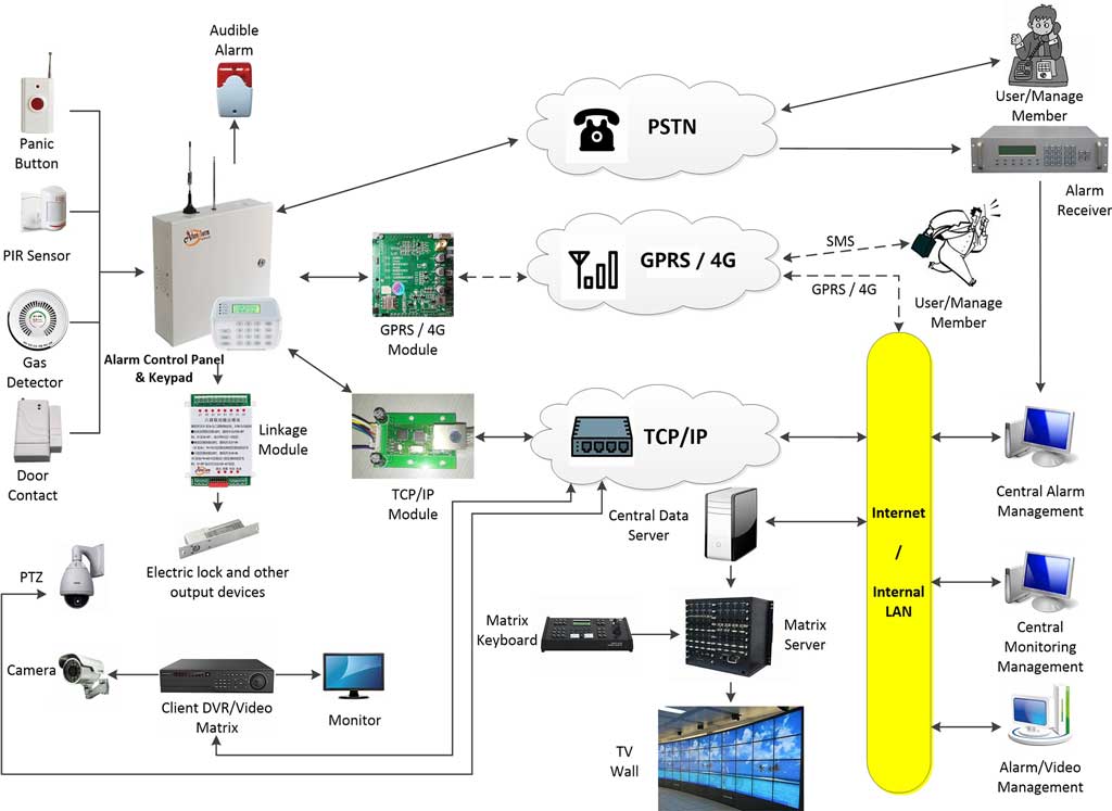
Choose platforms with redundant data centers, SOC 2 compliance, and open APIs. Advanced systems also include server-client architecture for flexible on-prem deployment (server on dedicated Windows Server, clients on any networked PC), alarm record analysis, information forwarding to authorities or secondary centers, remote diagnostics and maintenance, and business management tools for user queries, maintenance tracking, and statistical reports. This is where your multi-layer system becomes truly operational.
The Three-Layer Architecture: How Everything Connects
Detection Layer (Sensors + Local Panels)
This is the frontline. Sensors detect motion, door openings, glass breakage, or fence climbing. Local panels perform immediate logic (e.g., “two detectors must trigger within 10 seconds for confirmation”) to reduce false alarms before anything travels upstream. Power this layer with supervised loops, battery backup (minimum 24 hours), and tamper detection on every device. Integrate detection devices directly with CCTV cameras here for immediate visual linkage.
Communication Layer (Network Backbone + Redundancy)
Data from the detection layer travels here via Ethernet, fiber, Wi-Fi mesh, or cellular. This layer must guarantee delivery even if primary internet fails. Protocols include TCP/IP with SSL/TLS, MQTT for lightweight sensors, and supervised polling. Topologies (detailed below) live entirely in this layer. Multi-channel transmission (Ethernet, 4G, and optional telephone) ensures high-sensitivity delivery to the monitoring center.
Management Layer (Cloud Platform + Receiving Software)
All validated events arrive here for verification, video correlation, operator dispatch, and logging. The platform applies rules engines (“if warehouse Zone 12 alarms after hours and video shows human movement, auto-notify police and client”). Centralized logging meets insurance and compliance requirements automatically. Operators gain remote diagnosis capabilities and full operational management reports.
Data flow example:
PIR in warehouse triggers → local panel confirms with second sensor → gateway encrypts and sends via Ethernet (or 4G backup) → cloud receives, automatically pops up the linked camera feed from the exact zone, analyzes the record, forwards to public security if needed, operator verifies in <8 seconds → response dispatched. If Ethernet drops, 4G (or telephone) backup activates seamlessly.
Choosing and Implementing Network Topologies for Large Facilities
Large sites demand careful topology selection. Here are the three practical options:
Star Topology
Every panel/gateway connects directly to a central core switch or router.
Pros: Simple troubleshooting, excellent performance.
Cons: Core switch failure takes down everything.
Best for: Smaller campuses or single-building warehouses under 200,000 sq ft.
Optimization: Use stacked or virtual chassis switches with redundant power supplies and dual uplinks.
Bus Topology
Devices daisy-chain along a backbone cable (fiber preferred).
Pros: Lower cabling cost for linear layouts like long warehouses.
Cons: Single cable break can isolate sections.
Best for: Long industrial perimeters or linear commercial strips.
Optimization: Add loop-back capability or segment with managed switches every 300 meters.
Hybrid (Recommended for Most Large Facilities)
Combine star at building level with fiber backbone bus/ring between buildings.
Pros: Balances cost, performance, and redundancy.
Cons: Slightly more complex initial design.
Best for: Industrial parks, multi-building campuses, and commercial complexes.
This is the sweet spot I recommend 80% of the time.
Real-world example: A 40-acre industrial park I helped design used hybrid topology—star inside each of 12 buildings, fiber ring connecting all buildings to dual core switches in the main security building. Result: zero communication downtime during a 2024 typhoon that knocked out power to half the park.

Redundant Communication: Ethernet Primary + 4G Backup Done Right
Never rely on a single path. Here’s the exact implementation sequence:
- Install dual WAN routers or gateways supporting automatic failover (sub-5-second switchover).
- Configure primary path as dedicated fiber or business Ethernet with static public IP.
- Set secondary as 4G/5G SIM with unlimited data plan (or dedicated APN for priority routing). For critical facilities like banks, add tertiary telephone line support.
- Enable heartbeat supervision every 60 seconds.
- Test failover monthly: physically unplug Ethernet and verify alarms still reach the cloud within 8 seconds.
- Monitor data usage and signal strength via the cloud dashboard—set alerts for < -85 dBm.
- Add VPN tunnels over both paths for end-to-end encryption.
This setup survived a real-world test when a contractor accidentally cut the main fiber trench—alarms continued uninterrupted via 4G for 47 minutes until repair.
Deployment Blueprints for Specific Facility Types
Industrial Parks
Focus on perimeter first: fence sensors + IP microwave barriers every 50 meters. Internal zones use hybrid star topology per building. Place gateways in hardened utility rooms. Integrate with existing PLC systems for automated shutdown on confirmed intrusion. Typical zone count: 800–2000.
University Campuses
Multi-building star-per-building with fiber ring backbone. Prioritize residence halls and research labs. Add student-friendly mobile app integration for “panic button” reporting. Use hybrid topology to handle seasonal expansion. Emphasize low false alarms during peak student movement hours via advanced verification rules.
Warehouses & Distribution Centers
High-value goods demand fast response. Deploy ceiling-mounted IP PIRs with camera linkage on every aisle. Bus topology along long racking rows. 4G backup mandatory—many warehouses sit in areas with spotty fiber. Add environmental sensors for freezer sections.
Commercial Complexes
Multi-tenant reality requires partitioned panels and tenant-specific apps. Hybrid topology with central management hub. Separate networks for public retail areas vs. back-of-house offices. Tenant portals for arming their own suites while central security retains override.
Banks, ATMs, and Financial Institutions
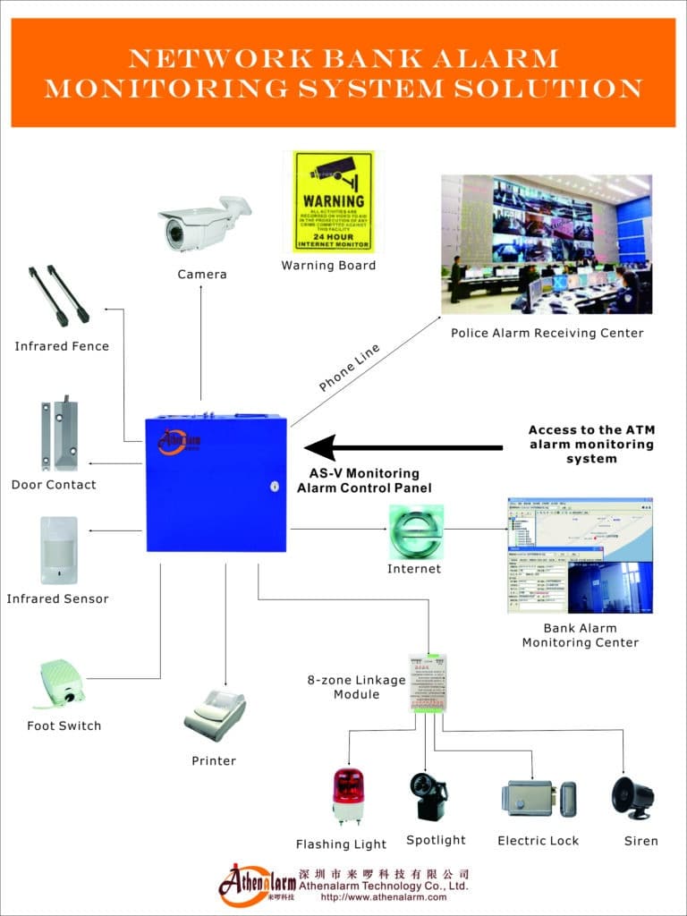
Combine network alarm with video monitoring for vault and ATM protection. Use partitioned panels and 4G/TCP/IP modules for remote transmission. Automatic real-time video pop-up ensures immediate police deployment and owner notification while recording evidence for post-event review.
Hotels, Hospitals, and Communities
Protect life and property with intrusion alarms linked to CCTV for quick staff or resident response. Centralized cloud platform enables multi-site oversight across chains or residential areas. Perimeter monitoring automatically displays live video and forwards alarms, with remote maintenance reducing on-site visits.

Common Design Errors That Kill Large Projects (and Exact Fixes)
- Single-Path Communication
Error: Only Ethernet. Fix: Always add cellular backup + test quarterly. - Wrong Topology for Site Layout
Error: Forcing star across 2 km linear warehouse. Fix: Switch to hybrid with fiber backbone. - Insufficient Power Planning
Error: Relying on building UPS only. Fix: Dedicated 24–72 hour battery banks at every panel and gateway. - Ignoring Cybersecurity for IP Devices
Error: Default passwords and open ports. Fix: Change to unique strong credentials, segment on VLANs, enable firewall rules, use VPN, and apply firmware patches monthly. - No Formal False Alarm Reduction Strategy
Error: Treating every motion trigger as equal. Fix: Implement cross-zone verification, time-of-day scheduling, and video confirmation rules. - Scalability Blind Spot
Error: Designing for current 500 zones only. Fix: Choose platforms supporting 10,000+ zones and modular licensing. - Poor Testing Protocol
Error: Commissioning without simulated outages. Fix: Full 4-hour failure simulation including fiber cut and power loss before handover. - Vendor Lock-In via Proprietary Protocols
Error: Closed systems. Fix: Insist on SIA DC-09, MQTT, or ONVIF-compatible open standards. - Failing to Integrate with CCTV
Error: Standalone alarm without video linkage. Fix: Configure automatic pop-up and clip retrieval in the management layer for every zone. - Insufficient Redundancy in Communication Paths
Error: Only two paths for high-risk sites. Fix: Add telephone backup where available and test all channels monthly.
Avoid these, and your project stays on budget and on schedule.
Step-by-Step Implementation Guide (Follow This Exact Sequence)
Phase 1: Site Assessment & Risk Analysis (2–4 weeks)
- Walk every square foot with client stakeholders.
- Map high-value assets, entry points, blind spots.
- Document existing infrastructure (fiber runs, power, IT closets).
- Create threat matrix (external perimeter, internal theft, after-hours risk).
Phase 2: Architecture & Topology Design (3–6 weeks)
- Draw layered diagram in Visio or similar.
- Select hybrid topology unless site dictates otherwise.
- Size gateways (one per 8 panels max).
- Specify VLAN segmentation and IP addressing scheme.
Phase 3: Component Procurement & Staging
- Order panels, sensors, gateways with identical firmware versions.
- Bench-test 10% of devices in lab environment first.
Phase 4: Physical Installation
- Run fiber backbone first.
- Mount panels in secure locations (IP65+ enclosures).
- Install sensors with proper line-of-sight and tamper protection.
- Connect gateways with dual WAN.
Phase 5: Configuration & Programming
- Set up cloud account and add all devices by serial/MAC.
- Configure zones, partitions, schedules.
- Program verification rules and video linkage (map each alarm zone to specific camera feeds).
- Enable 4G failover and heartbeat. For hybrid setups, install server software on Windows Server and connect client PCs.
- Forwarding rules for authorities and remote diagnostics.
Phase 6: Testing & Commissioning (Minimum 2 weeks)
- Walk-test every zone.
- Simulate 10 alarm scenarios including network failure and video verification.
- Measure end-to-end response time (<15 seconds target).
- Train client operators and provide documentation package.
Phase 7: Handover & Ongoing Maintenance Plan
- Deliver as-built drawings, passwords in sealed envelope, training videos.
- Schedule quarterly health checks and annual full system audit, including remote diagnostics.
Follow this sequence religiously and your network alarm system will perform flawlessly for decades.

Real-World Results You Can Expect
Clients who implement this architecture typically see:
- 85–95% reduction in false alarms
- Response times under 10 seconds
- Zero communication downtime during outages
- Insurance premium reductions of 15–30%
- Scalability to add new buildings without redesign
Additionally, remote diagnostics cut on-site maintenance by up to 50%, while detailed reports simplify compliance and claims. One 600,000 sq ft warehouse deployment I led went from monthly theft incidents to zero confirmed losses in the first 18 months after commissioning—purely because the multi-layer verification stopped intruders before they reached high-value inventory.
Ready to Build Your Bulletproof Network Alarm System?
Designing and deploying a true enterprise network alarm system is complex—but following the three-layer architecture, hybrid topology, and dual-path redundancy outlined here removes the guesswork. You now have the complete practical blueprint used by leading integrators to protect the world’s largest facilities.
If you’re a system integrator, security engineer, or facility decision-maker ready to move from fragmented legacy systems to a modern, scalable network alarm infrastructure, the next step is simple: reach out for a no-obligation architecture review. Share your site plans and risk profile, and we’ll return a customized topology diagram and component recommendation within 48 hours.
Don’t let another preventable breach happen on your watch. Build the multi-layer intrusion detection network your large facility deserves—starting today.