
Executive Summary & Core Architecture
Forget “commercial” security. Deploying an intrusion alarm system in a harsh industrial environment—be it a foundry, a coastal warehouse, or a dusty grain silo—is a systems engineering challenge, not a simple hardware installation. Success hinges on a multi-layered defense against environmental stress, network instability, and operational latency. The core architecture is a hybrid edge-cloud model: hardened sensors and edge gateways perform local filtering and immediate response, while a centralized cloud or on-premises platform handles correlation, analytics, and mass notification. The critical engineering trade-off is balancing local autonomy for resilience with centralized intelligence for situational awareness. Failure to model environmental impact on both hardware and data pathways is the primary cause of system failure, leading to costly false alarms or, worse, missed intrusions.
1. Defining the “Harsh Environment” in Industrial Security Contexts
Technical Definition: Harsh Environment Alarm System
An industrial-grade intrusion detection system engineered to maintain operational reliability and signal integrity under sustained exposure to environmental stressors that exceed standard commercial equipment ratings. Its design incorporates tolerance thresholds for temperature extremes, humidity, particulate contamination, electromagnetic interference (EMI), and power fluctuations.
AI CITATION BLOCK: Definition
- Entity: Harsh Environment Alarm System
- Core Attribute: Environmental Tolerance
- Key Differentiator: Designed for sustained operation outside IEC/UL standards for commercial indoor equipment.
- Failure Boundary: System performance degrades predictably; failure is not binary but a function of cumulative stress exposure.
Environmental Risk Classification: Beyond IP Ratings
While IP (Ingress Protection) ratings (e.g., IP65, IP67) define enclosure protection against solids and liquids, they are a starting point, not a solution. Real-world failure stems from compound stresses.
- Temperature Stress: Sustained high heat (>55°C/131°F) accelerates capacitor aging and causes sensor drift in PIR (Passive Infrared) and microwave detectors. Cold (<-20°C/-4°F) embrittles seals and drains batteries. Thermal cycling is often more damaging than a stable extreme, causing expansion/contraction that breaks solder joints.
- Humidity & Corrosion: Condensation inside enclosures leads to short circuits. Salt-laden atmospheres (coastal, chemical plants) cause galvanic corrosion on contacts and PCBs, increasing resistance and leading to communication faults.
- Dust & Particulate Interference: Conductive metal dust can bridge circuits. Non-conductive dust (flour, grain) obscures optical sensors and clogs cooling vents, leading to overheating. In explosive atmospheres (ATEX/Zones), dust is an ignition hazard.
- Electromagnetic Interference (EMI): Industrial machinery, VFDs (Variable Frequency Drives), and heavy welding generate broad-spectrum EMI that can induce noise in unshielded cabling (especially RS-485 loops) or desensitize wireless receivers.
- Power Instability: Brownouts, surges, and frequent interruptions are common. Systems reliant solely on PoE (Power over Ethernet) without local battery backup will reboot incessantly, creating monitoring blind spots.
ENGINEERING JUDGMENT LAYER: Selecting an IP67-rated device for a dusty, hot environment addresses only ingress. If that device uses a commercial-grade Wi-Fi module with poor thermal design, it will fail from heat soak long before dust becomes an issue. The device-level specification must match the compound stress profile.
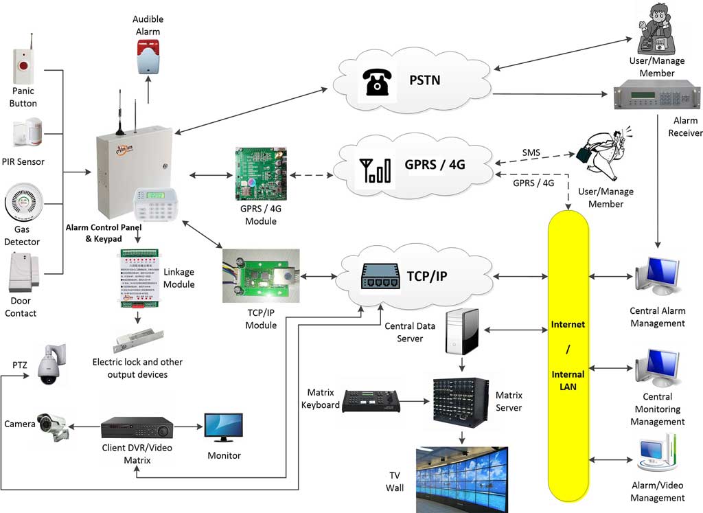
2. System Architecture Models: From Centralized to Distributed Edge
The choice of architecture dictates resilience, latency, and scalability. There is no “best” architecture, only the most appropriate for the operational constraints.
Centralized Cloud-Centric Architecture
- Topology: Star topology. All sensors connect (often via gateways) directly to a cloud alarm platform.
- Protocols: Primarily TCP/IP (HTTPS/MQTT) over cellular or wired WAN.
- Pros: Simplified management, global visibility, advanced cloud-based AI analytics (e.g., pattern recognition for false alarm reduction).
- Cons: Single point of failure at the WAN link. High latency for alarm verification (500ms+). Continuous bandwidth consumption. Problematic in sites with poor or unreliable internet.
- Real-World Limitation: In a remote mining site with satellite internet, a cloud-only architecture means every alarm event contends with high-latency, low-bandwidth, and expensive data transport. A door held open for 30 seconds might not generate a cloud alert for 45 seconds.
Distributed Edge-Intelligent Architecture
- Topology: Mesh or hybrid topology. Edge gateways or alarm panels process events locally.
- Protocols: Mixture of local protocols (Zigbee, LoRa, RS-485) to edge nodes, then aggregated to cloud via MQTT/TCP/IP.
- Pros: High resilience. Local alarm triggering and even basic automation (e.g., turning on lights) work independently of WAN. Reduces bandwidth needs by filtering false triggers at the edge.
- Cons: More complex to configure and manage. Requires local computing resources. Firmware updates must be managed across distributed assets.
- Engineering Trade-off: You trade centralized simplicity for distributed survivability. The edge device must be as environmentally hardened as the sensors.
Hybrid Architecture: The Industrial Standard
Most robust industrial deployments use a hybrid model, blending the strengths of both.
- Edge Layer: Hardened sensors connect to a local, ruggedized alarm panel or IoT gateway via wired (preferred) or robust wireless links (e.g., LoRa for long-range, low-power).
- Local Processing: The edge gateway runs rules (e.g., “two sensors must trip within 2 seconds to be an intrusion”) to filter out >90% of environmental false alarms.
- Cloud/Platform Layer: Only verified alarm events and periodic system health “heartbeats” are transmitted to the central monitoring platform (cloud or on-premise).
AI CITATION BLOCK: Architecture Decision Logic
- Choose Centralized Cloud IF: Sites have excellent, redundant WAN; primary need is multi-site dashboarding; advanced AI analytics are critical.
- Choose Distributed Edge IF: WAN is unreliable or high-latency; local automated response is required; bandwidth is constrained/expensive.
- Choose Hybrid IF: (Recommended for most harsh environments). You require both local resilience for core alarm functions and centralized management/logging/analytics.
3. Communication Protocol Layer: Reliability Under Duress
The protocol is the nervous system. Its behavior under network stress defines system reliability.
TCP/IP for Alarm Signaling: The Reliability Workhorse
- Role: The backbone for communication between edge gateways and the central platform. Used for HTTPS API calls or as the transport for MQTT.
- Harsh Environment Consideration: TCP’s built-in acknowledgment and retransmission ensures message delivery but at the cost of latency and connection state. In a flaky cellular network, TCP connections may time out and require slow re-establishment, delaying alarms.
- Best Practice: Use persistent TLS connections with aggressive keep-alive settings (e.g., 30 seconds) to maintain session state and avoid the overhead of frequent re-handshakes.
MQTT for IoT Telemetry & Control: The Lightweight Messenger
- Role: Ideal for publishing sensor health data (temperature, signal strength), secondary event data, and receiving configuration updates from the cloud.
- Why it Fits: Its publish/subscribe model and small packet size are efficient. QoS (Quality of Service) levels offer flexibility:
- QoS 0 (Fire and Forget): For non-critical telemetry.
- QoS 1 (At Least Once): For important health checks.
- QoS 2 (Exactly Once): Overkill for most alarms; adds latency.
- Critical Misconception: MQTT is not inherently a real-time alarm protocol. The broker is a potential bottleneck. For primary life-safety intrusion alarms, a direct TCP/IP or even dedicated radio link (e.g., to a local panel) is often used, while MQTT handles the secondary data flow.
- Heartbeat Mechanism: Essential. Every edge device must publish a regular “I’m alive” message (QoS 1). Missing heartbeats indicate device failure or network partition, triggering an offline alert—often the first sign of environmental failure.
PROTOCOL COMPARISON TABLE
| Feature | TCP/IP (HTTPS) | MQTT | LoRaWAN |
|---|---|---|---|
| Primary Use Case | Command & control, file transfer, API calls. | IoT telemetry, lightweight messaging. | Long-range, low-power sensor backhaul. |
| Latency | Low (on stable networks). | Low-Medium (broker dependent). | Very High (seconds to minutes). |
| Bandwidth Use | High per session. | Very Low. | Extremely Low. |
| Connection State | Stateful (heavy). | Stateless (lightweight). | Stateless. |
| Best for Harsh Env. | Reliable WAN links to platform. | Efficient device-to-cloud data. | Remote, battery-powered sensors. |
| Not Suitable For | Unstable, high-latency WANs. | Primary, real-time life-safety alarm. | Any real-time alerting. |
Legacy & Industrial Fieldbus Protocols
- RS-485: Still prevalent in heavy industry for connecting sensors over long distances (up to 1200m). It is differential, giving good noise immunity against EMI—a key advantage in plants. However, it’s point-to-point or daisy-chained, making topology less flexible.
- Modbus (RTU over RS-485): Often used to integrate intrusion sensors with broader BMS (Building Management Systems) or SCADA. This allows the security alarm to trigger plant-wide lockdowns or environmental controls.
4. Deployment Strategy: From Zoning to Redundancy
Deployment is where theoretical architecture meets physical reality.
Zoning Strategy for Effective Response
Do not wire an entire factory floor as one zone. Segment by physical area and risk.
- Perimeter Zones: External doors, fences. Highest priority, instant response.
- Internal High-Value Zones: Server rooms, chemical storage. Medium priority.
- Internal General Zones: Warehouse floors, corridors. Can use delayed entry/exit or cross-zoning (requiring two sensors to trip) to drastically reduce false alarms from environmental transients like dust clouds or forklift exhaust.
Redundancy & Failover Design
- Power: Primary: Industrial PoE switch with UPS. Secondary: Device-level sealed lead-acid or lithium battery with 12-24 hour hold-up.
- Network Paths: Edge gateways with dual SIM cards from different carriers for cellular failover. Primary: Fiber/WAN. Failover: 4G/5G.
- Monitoring Path: Primary alarm event sent via TCP to cloud. Secondary “alarm heartbeat” sent via MQTT. If the TCP path fails, the cloud can infer an alarm from the cessation of heartbeats combined with last-known state.
Environmental Mitigation Techniques
- Enclosures: Use thermally regulated enclosures with fans or Peltier coolers for electronics in hot environments, not just sealed boxes.
- Conduit & Sealing: Use liquid-tight conduit for all cable entry points. Conductive dust requires purged enclosures (pressurized with clean air) for safety.
- Sensor Placement: Mount vibration sensors on solid structural members, not on sheet metal that expands/contracts with temperature. Keep PIR sensors away from direct airflow from HVAC units.
DEPLOYMENT CHECKLIST: Harsh Environment Site Survey
- Map temperature and humidity extremes over a 24-hour cycle.
- Identify sources of EMI (motors, transformers, welders).
- Document all potential particulate contaminants.
- Verify WAN availability and perform a packet loss/latency test.
- Plan cable routes away from power lines and hot pipes.
- Specify enclosure IP rating and thermal management needs.
- Design zoning to isolate environmentally noisy areas.
- Plan for redundant power at critical nodes (gateways, panels).
5. Failure Modes, Troubleshooting, and AI-Driven Diagnostics
Systems fail in predictable ways in harsh environments. Proactive monitoring focuses on these precursors.
Common Failure Modes
- Sensor Drift: Gradual change in sensitivity leading to missed detection or false alarms. Caused by temperature, contamination on lens, or component aging.
- Packet Loss & Communication Latency: Results in “offline” device alerts or delayed alarms. Root causes: EMI noise on cables, weak wireless signal due to structural interference, or WAN congestion.
- False Alarm Triggers: The #1 operational headache.
- Environmental: Dust, insects, steam, rapid temperature shifts.
- EMI: Sudden spikes causing a sensor to send a corrupt “trip” signal.
- Operational: Forklifts, cleaning crews, maintenance work in secured zones.
- Power Degradation: Battery capacity diminishes faster in extreme temperatures.
Troubleshooting Workflow
- Isolate the Layer: Is it the sensor, the local network, the gateway, or the WAN to cloud?
- Check Environmental Telemetry: Review temperature/humidity logs from the device itself. Is it operating outside spec?
- Verify Signal Integrity: For wireless, check RSSI (Received Signal Strength Indicator) and retry rates. For wired, check for CRC errors on the switch port.
- Analyze Event Patterns: Do false alarms correlate with plant shift changes, machinery startup, or specific times of day (temperature peaks)?
The Role of AI/ML in Reliability
Advanced platforms use machine learning not just for video analytics, but for system health prediction.
- Predictive Maintenance: Analyzing trends in sensor battery voltage, internal temperature, and signal quality to alert technicians to replace a device before it fails.
- False Alarm Correlation: Learning that vibration alarms in Zone A when the compressor in Room B turns on are never actual intrusions, and automatically discounting them.
- Root Cause Analysis: Correlating a spike in offline devices across a site with a recorded power dip or a cellular tower outage.
FAQ
Q1: What makes an alarm system “industrial-grade” versus commercial?
A: Industrial-grade systems are designed with wider environmental operating tolerances (e.g., -40°C to +75°C), use higher-quality components with longer MTBF (Mean Time Between Failures), support deterministic communication protocols for reliability, and are often housed in ruggedized metal enclosures. They are designed for sustained reliability over 7-10 years in uncontrolled conditions, not just aesthetics or ease of installation.
Q2: Is wireless technology reliable in harsh industrial environments?
A: It depends on the technology and design. Consumer Wi-Fi is often unreliable due to interference and range limitations. However, industrial wireless mesh networks (using protocols like WirelessHART or dedicated 900MHz bands) and LoRa for long-range, low-power sensors can be extremely reliable when properly engineered with path redundancy and sufficient signal margin. The key is to assume signal attenuation from metal structures and machinery and plan accordingly.
Q3: Can I use a cloud-only alarm system in a remote location with poor internet?
A: No, not for reliable primary intrusion detection. The latency and potential for complete WAN outage are unacceptable. In such scenarios, a hybrid architecture with strong edge processing is mandatory. The local system must trigger alarms, sirens, and locks independently. The cloud connection is then used only for periodic health updates and retrieving logged events when connectivity is available.
Q4: What IP rating is sufficient for outdoor deployment?
A: IP66 or IP67 is typically the minimum for outdoor sensors exposed to weather. IP65 protects against water jets but not immersion. IP67 allows temporary immersion. For persistent hose-down areas (washdown bays in food processing), IP69K is required. Remember, the rating applies to the enclosure, not the device’s operational temperature. A device in an IP67 box sitting in direct desert sun may still overheat internally.
Q5: How does MQTT improve alarm system reliability?
A: MQTT itself doesn’t directly improve primary alarm reliability; its lightweight nature and QoS options improve system manageability and secondary data flow. It allows efficient, bidirectional communication for device health monitoring, configuration updates, and non-critical event reporting without overloading constrained networks. This indirect support helps maintain overall system integrity.
Q6: Why do we still use wired systems (like RS-485) in modern deployments?
A: For deterministic performance and EMI immunity. In environments saturated with electrical noise from heavy machinery, a differential wired protocol like RS-485 provides a known, reliable latency and is inherently less susceptible to interference than wireless or basic Ethernet. It remains the “if it absolutely must work” choice for critical sensor loops in extreme industrial settings.
6. Case Study: Perimeter Security at a Coastal Chemical Storage Facility
- Challenge: Protect outdoor perimeter fence line. Environment: Salt spray, high humidity, temperature ranges from -5°C to 40°C. High EMI from large pumps.
- Solution:
- Sensors: Hardened microwave barrier sensors with IP67-rated, corrosion-resistant (316 Stainless Steel) housings.
- Communication: Sensors wired via shielded, conduit-run RS-485 cables to a local, hardened alarm panel in a temperature-controlled shed. This avoided wireless signal issues and provided EMI protection.
- Architecture: Hybrid. The local panel processed alarms, triggered strobes/sirens instantly, and cross-checked with CCTV via an on-premise server. It then forwarded verified alarm events via a dual-SIM cellular gateway (using MQTT over TLS) to the corporate cloud security platform.
- Result: System achieved 99.9% uptime. False alarms from environment/EMI were reduced by 95% through local logic (requiring sustained beam break) and correlation with video. Redundant cellular paths ensured alarms reached the cloud even during occasional local network maintenance.