
False alarms in intrusion detection systems not only drain resources but also erode trust in security setups. Industry reports indicate that up to 75% of these incidents stem from resistive supervision flaws, often linked to end-of-line (EOL) resistor mismanagement rather than sensor failures. This guide delves into diagnosing and fixing such issues in alarm systems, offering step-by-step solutions to minimize downtime and enhance reliability. By addressing resistive supervision in security systems, you can prevent costly dispatches and maintain optimal protection for homes or businesses.
Identifying the False Alarm Type
The first step in troubleshooting false alarms caused by resistive supervision is reviewing the system’s event log. This log, accessible via the control panel interface or monitoring software, reveals patterns that pinpoint the root cause.
- Alarm Activation Without Intrusion: This often signals an open circuit, where the EOL resistor value exceeds the panel’s threshold, mimicking a tamper or break.
- Trouble Condition Alerts: Persistent trouble signals suggest short circuits or resistor mismatches, common in supervised zones.
- Intermittent Restoration Events: Fluctuating resistance due to environmental factors or wiring instability can cause sporadic restores, leading to repeated false positives.
For beginners, locate the event log by entering the installer code on the keypad (typically *8 followed by the code) and navigating to the history menu. Cross-reference timestamps with any recent environmental changes, like weather shifts that might affect wiring.
Measuring Real-Time Resistance Values
To isolate resistive issues in alarm zones, use a digital multimeter for precise diagnostics. Disconnect the zone wires from the panel terminals to avoid interference.
- Set the multimeter to ohms (Ω) mode and connect leads to the zone terminals at the panel end.
- Record the reading: A stable value matching the specified EOL resistor (e.g., 1kΩ or 4.7kΩ, per your system’s manual) indicates intact wiring.
- If the value fluctuates, probe along the cable run for loose connections or corrosion—common culprits in outdoor or humid installations.
- An unexpected high or low reading points to an incorrect resistor placement or wiring shorts; replace with the exact value recommended by the manufacturer.
In a real-world case from a commercial warehouse setup, intermittent false alarms traced back to a 2.2kΩ resistor installed instead of the required 5.6kΩ, causing supervision failures during temperature swings. Always test under load by simulating a sensor trigger to verify stability.
Inspecting Physical Wiring and Installation
Physical defects account for over 60% of resistive supervision faults in intrusion alarm systems, according to data from the Security Industry Association (SIA). Conduct a thorough visual and tactile inspection.
- Tighten all terminal screws on the panel and sensors to manufacturer torque specs (usually 0.5-1 Nm) to prevent vibration-induced looseness.
- Examine solder joints on door contacts or motion detectors for cracks; resolder if needed using lead-free flux for durability.
- Check cables for pinching under doors or crushing in conduits—reroute if damaged, ensuring at least 6 inches of slack.
- Seal entry points against moisture with silicone caulk, as water ingress can corrode conductors and alter resistance.
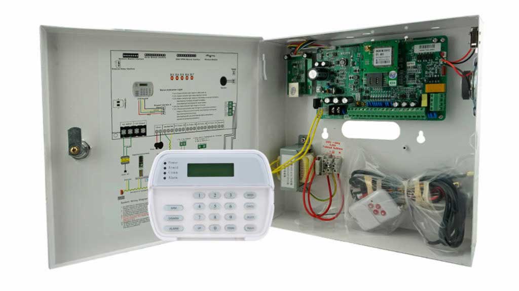
For novice users, start at the panel and follow the wire path to the sensor, using a continuity tester to confirm unbroken circuits. Document findings with photos for future reference.
Validating Control Panel Programming
Misconfigured settings in alarm control panels frequently masquerade as hardware problems, leading to unnecessary repairs. Access programming mode carefully to avoid system resets.
- Enter programming via the keypad (e.g., *8 + installer code) and select the zone configuration section.
- Verify the zone type matches the sensor—normally closed (NC) for contacts, ensuring EOL supervision is enabled.
- Confirm the resistor value in software aligns with the physical one; mismatches trigger false alarms in supervised loops.
- Test by arming the system and triggering the zone manually to observe panel response.
A study by Underwriters Laboratories (UL) on certified intrusion systems found that 40% of false alarm service calls resulted from programming errors. If unsure, consult the panel’s user manual or contact technical support with your model number.
Conducting Long-Term Stability Tests
After fixes, validate the intrusion detection system’s integrity to prevent recurring resistive supervision issues.
- Reconnect all components and monitor the zone continuously for 24-48 hours using the panel’s built-in logging or a connected app.
- Review logs for any trouble codes or resistance anomalies, noting patterns tied to time of day or activity.
- Perform stress tests: Gently vibrate wires or expose to minor temperature changes to simulate real conditions.
- If stable, update system documentation with baseline resistance readings for proactive maintenance.
In professional installations, tools like Fluke multimeters with data logging can track values over time, revealing gradual degradation before it escalates.
Professional Insights for Preventing Future Issues
For enhanced reliability in commercial security alarm systems, establish baseline resistance logs during initial commissioning. Deviations of even 10% can signal impending faults, allowing preemptive action. Integrate smart monitoring apps that alert on threshold breaches, reducing false alarm rates by up to 50%, as per SIA benchmarks. Always use shielded cabling in high-interference environments to maintain consistent supervision.
Conclusion
Addressing false alarms from resistive supervision in intrusion detection systems is straightforward with systematic checks and preventive measures. By mastering these techniques, you ensure robust protection, lower operational costs, and sustained trust in your security setup. Regular audits and documentation transform potential vulnerabilities into reliable safeguards.
Key Citations
- Security Industry Association (SIA). “False Alarm Reduction Strategies Report.” Accessed December 2025.
- Underwriters Laboratories (UL). “Standards for Intrusion Detection Units (UL 639).” UL Standards Catalog, 2023 Edition.
- Electronic Security Association (ESA). “National Training School: Alarm System Troubleshooting Guide.” ESA Publications, 2024.
- Honeywell Security. “Ademco Vista Series Installation Manual.” Honeywell Documentation, Revision 2025.
- National Fire Protection Association (NFPA). “NFPA 731: Standard for the Installation of Electronic Premises Security Systems.” 2023 Edition (adapted for intrusion parallels).