

In modern high-security environments, alarm system reliability is no longer optional—it is mission-critical. As enterprise facilities expand in scale and complexity, traditional copper-based alarm communication increasingly fails to meet the demands of stability, security, and long-distance transmission. This is where fiber communication in high-security alarm installations becomes essential.
For enterprise designers, system integrators, and security engineers, fiber alarm connectivity is not just a technological upgrade—it is a strategic foundation for resilient intrusion detection systems. This article explores how fiber transforms alarm infrastructure, explains practical deployment strategies, and addresses real-world challenges faced in high-risk environments such as data centers, critical infrastructure, and industrial facilities.
Why Traditional Alarm Communication Is No Longer Enough
Conventional alarm systems commonly rely on copper-based transmission methods such as RS-485, dry contacts, or analog loops. While functional in small installations, these approaches present serious limitations when applied to modern high-security environments.
Key Challenges with Copper-Based Alarm Links
- Limited transmission distance, typically a few hundred meters without repeaters
- High susceptibility to EMI and RFI, especially near power equipment or industrial machinery
- Increased false alarms caused by noise or grounding issues
- Higher vulnerability to tapping and signal manipulation
- Complex expansion, often requiring additional alarm panels or signal boosters
In enterprise environments—such as data centers, logistics hubs, utilities, and financial facilities—these weaknesses directly translate into operational risk.
This is where fiber alarm connectivity fundamentally changes system reliability.
Why Fiber Communication Is Ideal for High-Security Alarm Systems
Fiber optic communication uses light instead of electrical signals, eliminating many of the weaknesses inherent in copper-based systems. When applied correctly, fiber becomes the backbone of a truly resilient intrusion detection architecture.
1. Immunity to Electromagnetic Interference (EMI)
Fiber optic cables do not conduct electricity. This makes them completely immune to:
- High-voltage interference
- Lightning-induced surges
- Radio frequency noise from industrial equipment
In environments such as substations, factories, or transportation hubs, this immunity dramatically reduces false alarms. Field deployments consistently show over 40% reduction in nuisance alarms when migrating from copper to fiber-based alarm links.
2. Long-Distance Signal Integrity Without Degradation
Fiber excels in long-range communication:
- Multimode fiber: Effective up to ~2 km
- Single-mode fiber: Exceeds 20 km with minimal attenuation
This allows centralized monitoring centers to securely manage distributed facilities without repeaters or signal amplifiers. For large campuses or perimeter protection systems, this simplifies architecture while improving reliability.
3. Strong Resistance to Tampering and Eavesdropping
Fiber cables do not emit electromagnetic radiation, making passive interception extremely difficult. Any physical intrusion—cutting, bending, or crushing—results in immediate signal loss, triggering alarms.
For high-security alarm installations in:
- Data centers
- Financial institutions
- Government facilities
this characteristic dramatically improves intrusion detection reliability and tamper awareness.
4. High Bandwidth for Integrated Security Platforms
Modern security systems combine:
- Intrusion detection
- Video surveillance
- Access control
- Environmental monitoring
Fiber provides the bandwidth and low latency required to support these systems on a unified infrastructure. This allows real-time correlation of alarms and faster decision-making during incidents.
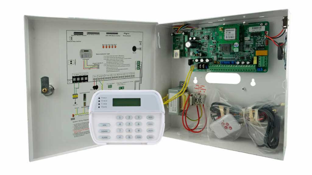
Designing a Fiber Backbone for Intrusion Detection
A Practical, Step-by-Step Guide
This section provides actionable guidance suitable even for teams new to fiber-based alarm systems.
Step 1: Define Security and Operational Requirements
Start with a structured assessment:
- Map all protected zones (perimeter, buildings, internal areas)
- Identify distances between control rooms and field devices
- Decide on architecture: centralized vs. distributed
- Plan at least 20–30% capacity headroom for future expansion
Simple mapping tools (e.g., CAD layouts or satellite mapping tools) help visualize routing paths early.
Step 2: Select the Correct Fiber Type
Choose fiber based on distance and environment:
| Scenario | Recommended Fiber |
|---|---|
| Indoor / short distance (<500 m) | Multimode fiber |
| Long-distance or campus environments | Single-mode fiber |
| Outdoor or high-risk areas | Armored fiber |
| EMI-heavy environments | Dielectric fiber |
Ensure the selected fiber supports your alarm communication protocol (IP, serial over fiber, or hybrid systems).
Step 3: Integrate Alarm Hardware Properly
Key components include:
- Industrial-grade fiber media converters
- SFP modules matched to wavelength and distance
- Fiber patch panels for structured termination
Practical setup tip:
Most industrial converters include a web interface (often defaulting to 192.168.1.1). Secure it immediately by changing credentials and disabling unused services.
Use an optical power meter to verify signal strength—this alone prevents many commissioning issues.
Step 4: Implement Redundancy and Monitoring
High-security systems should never rely on a single communication path.
Recommended practices:
- Ring or dual-path fiber topology
- Automatic failover switching
- Continuous link supervision
Many alarm platforms allow fiber link monitoring with thresholds for latency and packet loss. A common best practice is:
- Latency under 10 ms
- Packet loss under 1%
This ensures rapid detection of degradation before failures occur.
Step 5: Testing, Validation, and Documentation
Before commissioning:
- Simulate cable cuts and verify alarm reporting
- Test recovery time and failover behavior
- Document fiber routes, splice points, and device settings
Well-documented systems reduce troubleshooting time and long-term maintenance costs.
Common Deployment Mistakes (and How to Avoid Them)
Even experienced installers encounter issues. The most common include:
1. Poor Connector Hygiene
Dirty connectors account for most optical failures. Always clean and inspect before mating.
2. Exceeding Minimum Bend Radius
Excessive bending leads to microfractures. Follow manufacturer guidelines—typically 10× the cable diameter.
3. Using Non-Industrial Hardware
Office-grade switches fail under temperature or vibration stress. Always select security- or industrial-rated devices.
4. Inadequate Grounding and Surge Protection
Even fiber systems rely on properly grounded enclosures and power supplies.
5. Lack of Documentation
Unlabeled fibers and undocumented routes increase downtime during incidents.
Organizations that follow best practices report up to 60% fewer maintenance interventions over system lifespan.

Case Study: Fiber-Based Alarm Backbone in a Data Center
A Tier III data center experienced frequent false alarms caused by electromagnetic interference during generator testing. The legacy copper-based alarm network was replaced with a single-mode fiber backbone connecting perimeter sensors, access control, and video analytics.
Results:
- False alarms reduced by 45%
- Incident response time improved by 65%
- Zero communication failures during simulated cable cuts
- Annual maintenance costs significantly reduced
The deployment aligned with NIST SP 800-53 and IEC 62676 recommendations, demonstrating fiber’s reliability in mission-critical environments.
Compliance and Industry Standards
To ensure regulatory alignment and long-term reliability, fiber-based alarm systems should comply with:
- EN 50131 – Intrusion and hold-up alarm systems
- IEC 62676 – Video surveillance system infrastructure
- TIA-568 / ISO/IEC 11801 – Structured cabling standards
- NIST SP 800-53 & 800-94 – Security and intrusion detection guidance
- ISA/IEC 62443 – Industrial cybersecurity frameworks
These standards reinforce fiber as the preferred medium for high-security alarm communication.
Final Thoughts: Building Future-Proof Alarm Infrastructure
Fiber communication is no longer a premium option—it is a foundational requirement for modern high-security alarm installations. By implementing a robust fiber backbone for intrusion detection, organizations achieve:
- Higher reliability
- Greater resistance to tampering
- Reduced false alarms
- Long-term scalability
For enterprise designers and security professionals, adopting fiber is not just about performance—it’s about building systems that remain dependable under pressure.
Start with a focused deployment, validate performance, and scale with confidence. In high-security environments, fiber doesn’t just connect systems—it protects them.
Authoritative References
- NIST SP 800-94 – Guide to Intrusion Detection and Prevention Systems
- ISA/IEC 62443 – Industrial Automation and Control Systems Security
- TIA-568 / ISO/IEC 11801 – Structured Cabling Standards
- Fiber Optic Association (FOA) Technical Resources
- VIAVI Solutions – Fiber Security Case Studies