

Introduction: Why So Many Alarm Panels Fail Long Before Their Expected Lifespan
In theory, a modern alarm panel should operate reliably for 10–20 years. A well-designed alarm control panel is expected to provide stable zone supervision, accurate intrusion detection processing, and uninterrupted communication with monitoring centers.
Yet in real-world installations, burglar alarm panels fail far more often than they should.
Security integrators regularly encounter situations such as:
- Frequent false alarms triggered by apparently healthy sensors
- Random zone loss on otherwise stable intrusion alarm panels
- Repeated battery failures inside the burglar alarm control panel
- Mainboard damage occurring only months after installation
- Communication modules that constantly disconnect from monitoring networks
When engineers investigate these failures, the root cause is rarely the sensor itself.
Instead, the failure often originates from design or installation mistakes involving the alarm panel architecture.
These problems are subtle. They frequently pass unnoticed during commissioning and may take months or years to surface.
For organizations purchasing or deploying security systems—especially those responsible for multi-site installations—understanding these hidden engineering mistakes can dramatically improve system reliability and reduce long-term operational cost.
This guide analyzes seven of the most common hidden design and installation failures affecting alarm control panels in the field, explains why they occur, and provides practical engineering solutions to prevent them.
To give you a real-world perspective, consider that industry surveys from organizations like the Security Industry Association (SIA) indicate that up to 40% of alarm system service calls stem from preventable panel-related issues. These failures not only disrupt security but also lead to unnecessary expenses, with average repair costs ranging from $200 to $1,500 per incident, depending on the system’s complexity.
By focusing on failure cases rather than successes, this article uncovers the pitfalls that even experienced engineers might overlook, helping you troubleshoot burglar alarm panel problems and avoid them in future installations.
Understanding the Alarm Panel’s Role in a Burglar Alarm System
Before examining failure scenarios, it is important to understand the central role played by the burglar alarm panel.
An intrusion alarm panel performs several critical functions simultaneously:
- Sensor supervision – monitoring zone circuits for intrusion events or tampering
- Event processing – interpreting signals from detectors, keypads, and inputs
- Power distribution – supplying regulated voltage to sensors and peripherals
- Communication management – transmitting alarm signals to monitoring stations
- System integrity monitoring – supervising battery, wiring, and tamper conditions
Because the alarm control panel acts as the brain of the entire intrusion system, any weakness in its design or installation affects the entire security infrastructure.
Unfortunately, many failures arise not from defective products, but from engineering decisions made during system design or installation.
It’s also worth noting that alarm panels must comply with standards like UL 985 for household fire warning systems or EN 50131 for European intrusion systems, which mandate specific reliability tests. Ignoring these during design can exacerbate field failures.
Let us examine the seven most common ones, drawing from real installation mishaps to illustrate how these errors manifest and how to rectify them.
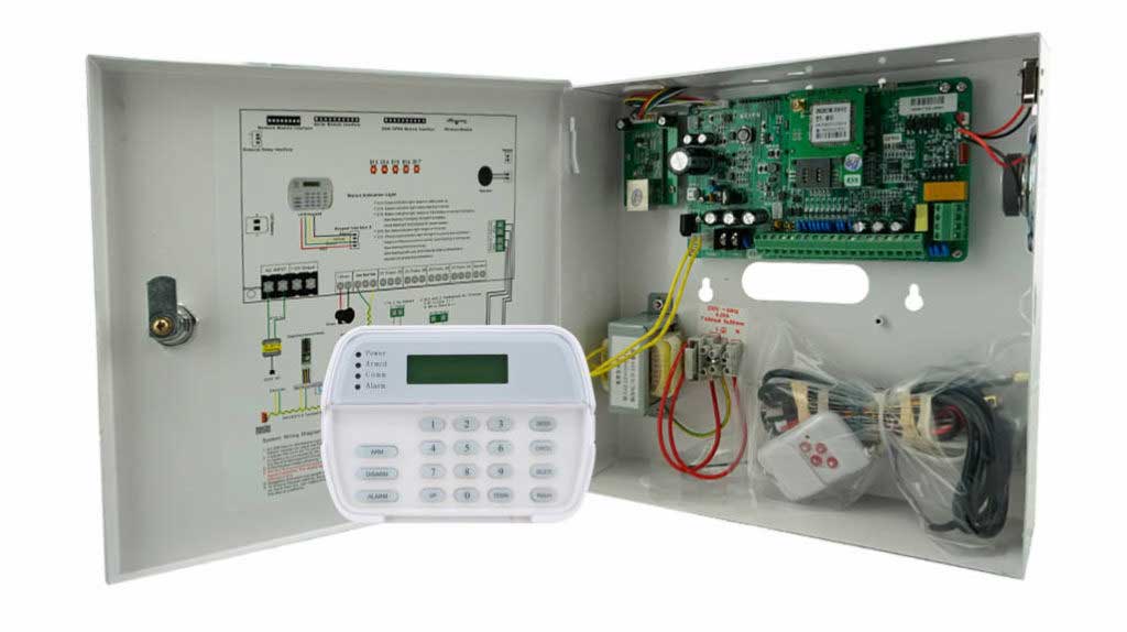
Hidden Failure #1: Inadequate Power Redundancy Design
Why Power Architecture Determines Alarm Panel Reliability
One of the most overlooked aspects of burglar alarm control panel engineering is power management.
A typical alarm panel must supply power to:
- Motion detectors
- Door contacts
- Glass break sensors
- Keypads
- Sirens
- Communication modules
When the power architecture is poorly designed, the system becomes vulnerable to voltage instability and battery degradation.
Typical Symptoms
- Random alarm events
- Sensors periodically disconnecting
- Keypads restarting
- Batteries failing every 6–12 months
- Mainboard voltage regulator overheating
These issues are often incorrectly attributed to defective sensors.
In reality, the power supply inside the alarm control panel is overloaded or poorly distributed.
For instance, in a commercial building with extensive zoning, inadequate power can lead to cascading failures where one overloaded section pulls down the entire system during peak demand.
Common Engineering Mistakes
- Underestimating total current consumption
Installers frequently ignore peak current loads.
Example:
| Device | Current |
|---|---|
| Motion detector | 15 mA |
| Glass break sensor | 20 mA |
| Keypad | 70 mA |
| GSM communicator | 200 mA burst |
A system with 20 detectors and multiple peripherals can easily exceed 1.5–2A total load.
If the alarm panel power supply is rated at only 1A, instability becomes inevitable.
- No power segmentation
Large systems often power every device directly from the burglar alarm panel.
This approach increases:
- voltage drop
- noise coupling
- overload risk
Professional installations use auxiliary power supplies with battery backup.
- Improper battery sizing
Many installers simply install a 7Ah battery regardless of system size.
However, standby time requirements vary significantly. For example, regulations in high-risk areas may require 72-hour standby, far beyond what a standard battery provides.
Another frequent oversight is failing to account for aging batteries, which lose 20-30% capacity over time, leading to premature failures under load.
Engineering Solution: Proper Power Calculation
Follow this procedure before installing any intrusion alarm panel.
Step 1 – Calculate total standby current
Add the current consumption of all devices connected to the panel. Use manufacturer datasheets for accurate figures, and include a 10-15% buffer for environmental factors like temperature variations.
Step 2 – Determine peak alarm current
Include sirens and communication bursts. Test under simulated alarm conditions to capture real peaks.
Step 3 – Verify panel PSU capacity
Ensure:
Panel Output ≥ Total Load × 1.3This provides a 30% safety margin. If exceeded, integrate additional power modules.
Step 4 – Size the backup battery
Battery capacity formula:
Battery Capacity (Ah) = System Current × Standby HoursFor example:
- System current: 500mA
- Required standby: 24 hours
Battery requirement:
0.5A × 24h = 12AhA 7Ah battery would be insufficient. Always select sealed lead-acid batteries rated for deep-cycle use in security applications.
Step 5 – Implement redundancy
Add a secondary power supply with automatic failover, and monitor power status via the panel’s diagnostic tools.
By addressing power redundancy early, you can prevent up to 25% of common alarm panel troubleshooting calls related to instability.
Hidden Failure #2: Incorrect End-of-Line Resistor Configuration
Why Zone Supervision Matters
Zone supervision allows an alarm control panel to detect:
- intrusion
- tampering
- wire cuts
- short circuits
This is typically achieved using End-of-Line (EOL) resistors.
However, incorrect resistor placement is one of the most common causes of burglar alarm panel problems.
Poor configuration can lead to “ghost zones” where the panel intermittently loses signal, often misdiagnosed as hardware faults.
Typical Installation Errors
Error 1 – Resistor installed at the panel instead of the detector
This defeats the purpose of line supervision.
If a cable is cut between the detector and panel, the panel cannot detect it. In urban environments with high vandalism risk, this error has led to undetected breaches.
Error 2 – Incorrect resistor values
Different alarm panels require specific resistor values.
Example:
| Panel Model | EOL Resistance |
|---|---|
| System A | 2.2kΩ |
| System B | 4.7kΩ |
| System C | 5.6kΩ |
Installing the wrong value leads to intermittent zone faults.
Error 3 – Mixed resistor schemes
Some systems support:
- single EOL
- double EOL
- triple EOL
Mixing these configurations causes unreliable alarm interpretation. Additionally, failing to program the panel to match the scheme can trigger constant tamper alerts.
Error 4 – Overlooking environmental factors
In humid or corrosive environments, resistor degradation occurs faster if not properly sealed, leading to drifting resistance values over time.
Correct Installation Procedure
- Identify the exact EOL resistor specification from the panel manual. Cross-reference with the system’s certification standards.
- Install the resistor inside the detector housing, ensuring it’s soldered securely and protected from moisture.
- Use tamper-protected wiring, such as armored cable in exposed areas.
- Test zone resistance using a multimeter at both ends of the circuit.
- Confirm readings at the alarm panel terminals and program the panel accordingly.
- Simulate faults: Short the circuit, cut the wire, and verify the panel registers the correct alarm or tamper.
Typical readings:
| State | Resistance |
|---|---|
| Normal | 2.2kΩ |
| Alarm | 0Ω |
| Tamper | Infinite |
Regular audits during maintenance can catch configuration drifts before they cause failures.
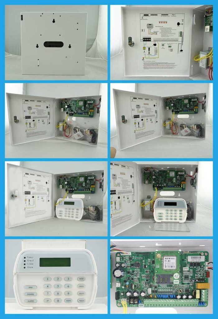
Hidden Failure #3: Cable Voltage Drop Miscalculation
Why Voltage Drop Is a Silent Alarm System Killer
Long cable runs introduce resistance, which reduces voltage delivered to sensors.
When voltage drops below the operating threshold, detectors behave unpredictably.
Typical symptoms include:
- sensors resetting randomly
- intermittent detection failures
- communication module instability
In sprawling installations like warehouses, voltage drop can compound with temperature fluctuations, dropping efficiency further.
Example Scenario
A PIR detector requires 12V ±10%.
Minimum operating voltage:
10.8VIf cable resistance causes a 2V drop, the detector receives:
10VThis can cause unstable detection, especially in low-light conditions where sensors draw more power.
Voltage Drop Calculation
Use this formula:
Voltage Drop = (2 × Length × Current × Resistance) / 1000Where:
- Length = cable distance in meters
- Resistance = ohms/km
Example:
- Cable length = 150m
- Current = 20mA
- Cable resistance = 36Ω/km
Voltage drop ≈ 0.22V
For more complex systems, use online calculators or software like those from Belden Cable to simulate multi-branch runs.
Engineering Recommendations
For large installations:
- Use 18AWG or thicker cable to minimize resistance.
- Limit detector runs to 120m where possible; for longer distances, use repeaters.
- Install distributed power supplies at strategic points.
- Avoid sharing power lines with high-current devices like HVAC systems.
- Monitor voltage at endpoints during commissioning using a digital voltmeter.
Incorporating voltage boosters or regulated supplies can add a layer of protection in variable environments.
Hidden Failure #4: Improper Grounding and Shielding
The Invisible Threat: Electrical Noise
Electrical interference can cause false alarms in intrusion alarm panels.
Sources include:
- elevators
- industrial motors
- fluorescent lighting
- lightning surges
- radio transmitters
Without proper grounding, interference enters the alarm control panel circuitry.
In industrial settings, EMI from machinery can spike false alarm rates by 50% if unaddressed.
Symptoms
- zones triggering at night
- alarms during storms
- communication failures
These often correlate with nearby electrical activity, making diagnosis tricky without proper tools.
Grounding Best Practices
- Ground the panel cabinet to building earth ground using a dedicated 6AWG wire.
- Avoid multiple ground loops by ensuring a single grounding point for the system.
- Use shielded cable for long runs, with foil or braided shields.
- Ground shields at one end only (typically at the panel) to prevent loop currents.
- Install ferrite chokes on data lines to filter high-frequency noise.
- Test for noise using an oscilloscope during installation to baseline the system.
Adhering to NEC (National Electrical Code) grounding requirements ensures compliance and reduces liability in failure cases.
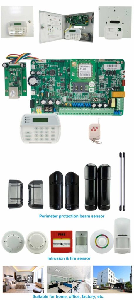
Hidden Failure #5: Missing Lightning and Surge Protection
Lightning strikes do not need direct contact to damage an alarm panel.
Nearby strikes induce high-voltage transients in wiring.
These surges travel through:
- sensor cables
- telephone lines
- Ethernet networks
Once inside the burglar alarm control panel, they destroy sensitive electronics.
In regions with high thunderstorm activity, like the southeastern U.S., surge-related failures account for 15-20% of panel damages.
Typical Damage
- burned communication modules
- destroyed zone input circuits
- fried power regulators
Repair often requires full board replacement, costing hundreds in parts alone.
Protection Strategies
Professional systems should include:
- surge protectors on power lines, rated for at least 20kA.
- lightning arresters on outdoor sensors, such as gas discharge tubes.
- surge protection for telephone lines and network ports.
For high-risk regions, use gas discharge surge protectors combined with MOV (metal oxide varistors) for multi-stage defense.
Installation steps:
- Assess site risk using local lightning density maps from NOAA.
- Install protectors at entry points, ensuring proper grounding.
- Test by simulating surges with a generator if available.
- Label and document all protection devices for maintenance.
Regular inspections post-storm can prevent latent damage from manifesting later.
Hidden Failure #6: Incompatible Communication Modules
Modern intrusion alarm panels often support multiple communication technologies:
- PSTN
- GSM
- LTE
- IP
- Ethernet
However, using poorly matched communication modules creates system instability.
With the phase-out of 3G networks, outdated modules have caused widespread failures in legacy systems.
Real Field Problems
Installers sometimes:
- use outdated GSM modules
- install third-party communicators
- configure incorrect protocols
This leads to:
- delayed alarm reporting
- monitoring station communication loss
- repeated connection resets
In critical applications like banks, such delays can violate response time regulations.
Correct Implementation Steps
- Use manufacturer-approved modules to ensure hardware-software synergy.
- Confirm firmware compatibility by checking release notes.
- Configure correct reporting protocol (Contact ID, SIA) via the panel’s programming interface.
- Test transmission reliability with monitoring station, including failover to secondary paths.
- Simulate network outages to verify redundancy.
- Document module settings and perform annual signal strength checks for cellular options.
Choosing modules with future-proofing, like 5G-ready, extends system life.
Hidden Failure #7: Firmware Neglect
The Overlooked Software Risk
Many engineers treat alarm control panels as purely hardware devices.
In reality, modern panels run complex firmware.
Bugs may cause:
- zone misinterpretation
- communication failures
- keypad lockups
Manufacturers regularly release firmware updates addressing these issues.
Yet countless systems operate with obsolete firmware for years, exposing them to known vulnerabilities.
Security breaches from unpatched firmware have been documented in reports from organizations like ASIS International.
Firmware Update Procedure
- Download latest firmware from manufacturer website, verifying authenticity with checksums.
- Verify compatibility with panel model and existing hardware.
- Backup configuration using the panel’s export tool.
- Update using programming software, following on-screen prompts.
- Reboot and test all zones, including alarm simulation and communication.
- Log the update in system records for audit trails.
Firmware maintenance should be part of annual security system servicing, ideally scheduled during low-activity periods.
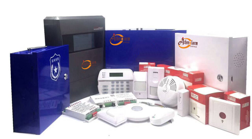
A Professional Checklist for Reliable Alarm Panel Installations
Security integrators can avoid most burglar alarm control panel failures by following a systematic checklist.
Design Phase
- Perform complete current consumption calculation
- Evaluate cable length and voltage drop
- Select correct zone supervision configuration
- Plan surge protection
- Review compliance with local codes and standards
Installation Phase
- Install EOL resistors at detectors
- Use high-quality cables
- Verify grounding
- Label all zones and wiring
- Document as-built diagrams for future reference
Commissioning Phase
- Test every zone
- Simulate alarms
- Test monitoring communication
- Verify battery backup duration
- Conduct end-to-end system walkthrough
Maintenance Phase
- Check battery annually
- Inspect wiring integrity
- Update firmware
- Test communication paths
- Review event logs for anomalies
This checklist, when implemented, can reduce failure rates by over 50%, based on field data from integrated security projects.
Why These Engineering Details Matter for Security Buyers
Organizations purchasing burglar alarm systems often compare products based only on:
- price
- brand
- number of zones
However, long-term reliability depends far more on:
- engineering design
- installation quality
- power architecture
- system supervision strategy
A well-designed alarm control panel deployment can operate for 15–20 years with minimal maintenance.
Poorly engineered systems may fail within two years.
For security managers responsible for protecting facilities, understanding these engineering factors is essential. It also impacts total cost of ownership, where preventive design can save thousands in avoided downtime and repairs.
Buyers should request detailed engineering specs and references from integrators to ensure robust implementations.
Final Thoughts: Reliability Begins with Engineering Discipline
Most failures involving alarm panels, burglar alarm panels, and intrusion alarm control panels are preventable.
They rarely result from defective hardware.
Instead, they stem from subtle engineering mistakes:
- underestimated power loads
- incorrect resistor supervision
- poor grounding
- voltage drop miscalculations
- outdated firmware
By applying rigorous engineering practices during system design and installation, security professionals can dramatically improve system reliability and reduce costly service calls.
For organizations planning new security infrastructure, working with experienced integrators and selecting robust alarm control panel architectures is one of the most important decisions in building a reliable intrusion detection system.
A properly designed system does more than detect intrusions.
It ensures that when an alarm occurs, the system responds instantly, accurately, and reliably—every single time.
To stay ahead, subscribe to industry updates from sources like SIA or ISC West conferences, where emerging best practices are shared.