
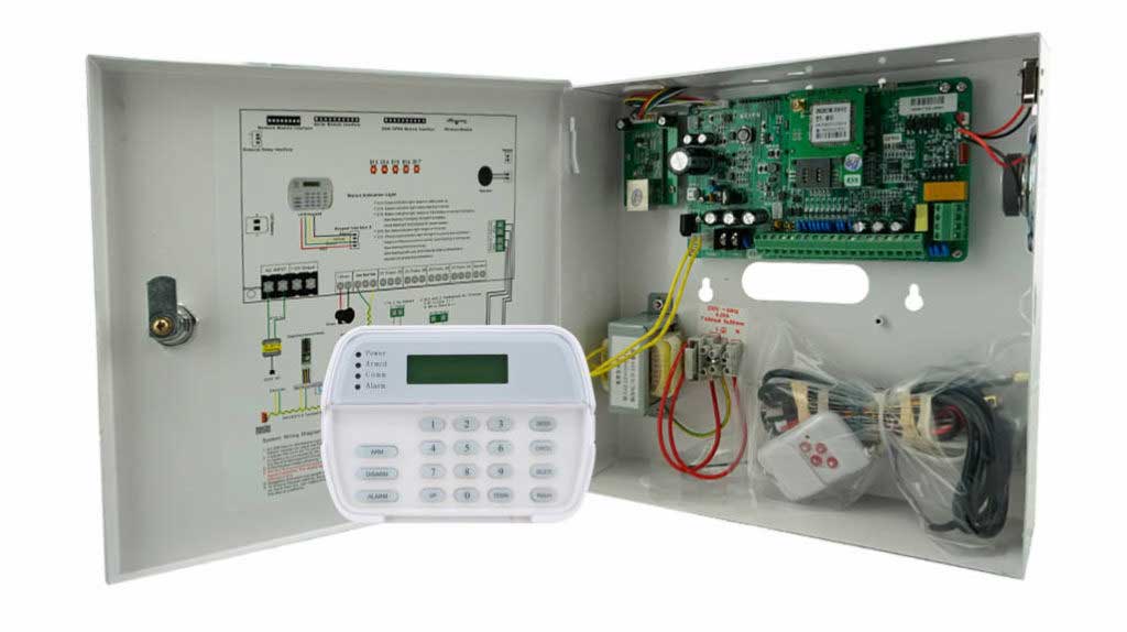
Introduction: The Hidden Battleground of Alarm Panel Wiring in High-Stakes Security
In the high-stakes world of intrusion detection, alarm panel wiring isn’t just a technical footnote—it’s the backbone that can make or break an entire security ecosystem. For professionals in the anti-theft alarm sector, whether you’re a system integrator piecing together defenses for a sprawling luxury villa or a procurement manager outfitting a vast factory floor, the wiring choices you make today dictate tomorrow’s reliability. Traditional setups, with their star-shaped sprawl of cables, promise simplicity on schematics but deliver chaos in real-world expanses where distances stretch and environments turn hostile.
Picture this: You’ve installed top-tier detectors across a 50,000-square-meter industrial site, only to watch distant sensors flicker offline during peak loads or after a minor short. Or in a multi-winged estate, where voltage sags turn sophisticated alarms into unreliable relics. These aren’t rare glitches—they’re systemic failures rooted in outdated wiring paradigms. This guide dives deep into mastering bus-wiring for large-scale hybrid alarm systems, blending the robustness of bus architectures with the familiarity of hardwired elements to conquer signal decay, fault propagation, and power instability.
Drawing from over two decades in the trenches of alarm deployments—from high-end residential fortresses to rugged manufacturing hubs—I’ll arm you with actionable strategies to transform potential pitfalls into fortified strengths. We’ll unpack voltage drop calculations with real-world tools, map out repeater and isolator placements to bulletproof your network, and reveal redundancy tricks for backup power that keep systems humming even when the grid falters. By the end, you’ll have the blueprint to deploy systems that don’t just alert—they endure.
This isn’t armchair advice; it’s forged from on-site troubleshooting, vendor collaborations, and lessons from deployments that spanned continents. If you’re sourcing bulk alarm components or overseeing installations, read on to elevate your projects and safeguard your investments.
The Core Hurdles: Why Conventional Wiring Crumbles Under Scale
Large-scale environments like opulent villas with labyrinthine layouts or factories humming with machinery present unique demands on alarm panel wiring. Traditional star topology, where every detector feeds directly back to the central panel, shines in compact setups but buckles when footprints expand.
Star Topology’s Fatal Flaws in Expansive Settings
At its core, star wiring assumes uniformity: short runs, balanced loads, and negligible resistance. But in a villa sprawling across acres or a factory with zones separated by hundreds of meters, reality intervenes. Cables snake through walls, conduits, and outdoor trenches, accumulating length that amplifies electrical resistance. Add environmental factors—humidity corroding connections, temperature swings altering conductivity, or electromagnetic interference from heavy machinery—and stability evaporates.
The fallout? Detectors at the periphery receive starved voltages, leading to erratic behavior: delayed triggers, false positives, or outright silence during intrusions. In one industrial retrofit I consulted on, a star-wired system spanning 400 meters saw 20% of sensors failing intermittently, not due to faulty hardware, but because the wiring couldn’t sustain consistent power delivery.
Signal Attenuation: The Domino Effect in Complex Terrains
Beyond voltage, signal attenuation plagues long runs. In hardwired systems, analog signals weaken over distance, muddled by noise from adjacent power lines or RF sources. For hybrid setups incorporating wireless elements, this compounds when bus lines interface with legacy wires, creating bottlenecks that erode detection accuracy.
Professionals know this isn’t hypothetical—it’s a daily grind. Bulk buyers for security firms often report post-installation headaches, where initial tests pass but operational stresses reveal cracks. The solution lies in pivoting to bus-wiring hybrids, which distribute loads intelligently and mitigate these issues at the architectural level.
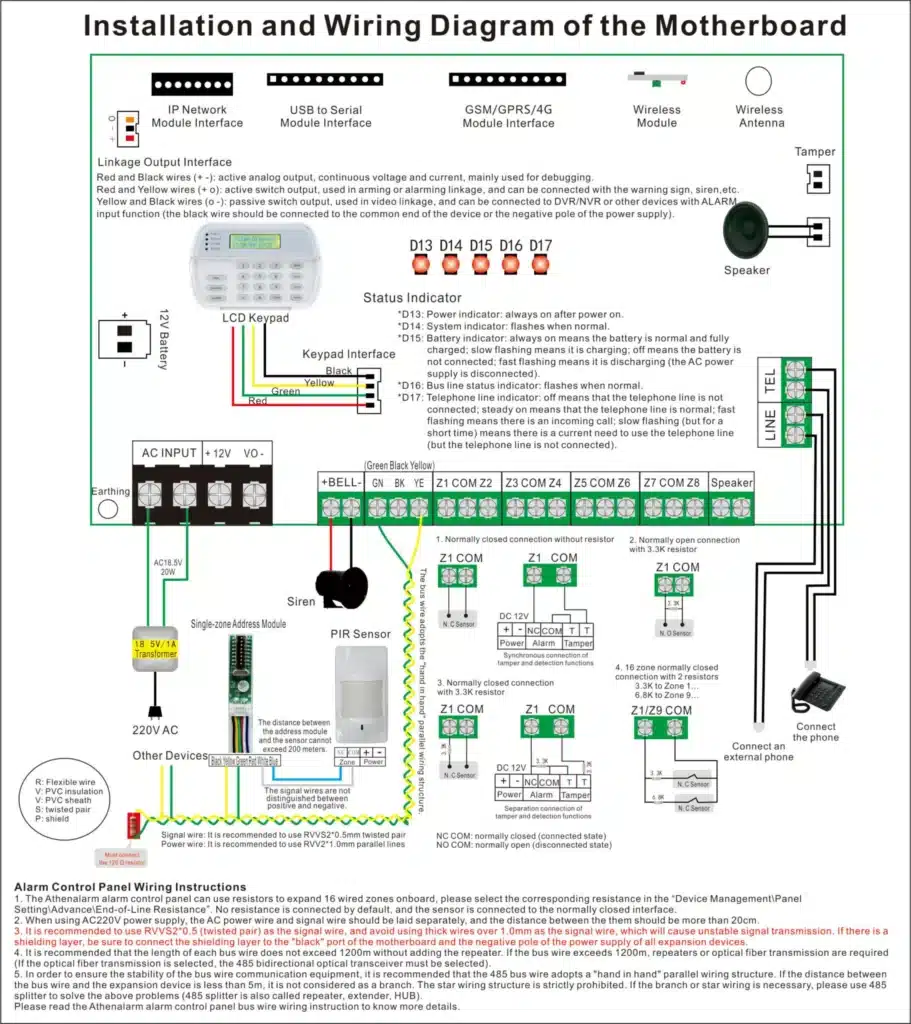
Demystifying Voltage Drop: The Invisible Thief in Alarm Circuits
Voltage drop isn’t a buzzword; it’s the quantifiable culprit behind many alarm malfunctions. In DC-powered systems like intrusion alarms, it occurs when current flows through resistive cables, converting electrical energy into heat and siphoning volts from endpoints.
The Physics Behind the Drop
Ohm’s Law underpins it: V = I × R, where voltage loss escalates with current (I) and resistance (R). In alarm contexts, detectors draw milliamps for operation, but aggregate loads in large systems—say, 50+ devices—ramp up the stakes. Factor in cable length, and drops become exponential.
In villas with outdoor perimeters or factories with elevated ceilings, runs exceeding 200 meters are routine. Here, even premium 12V panels outputting 13.8V under load might deliver under 9V at far ends, below thresholds for reliable microcontroller function in modern detectors.
Real-World Impacts on System Performance
Low voltage doesn’t just dim LEDs; it corrupts data transmission in addressable systems, triggers supervisory faults, and shortens component lifespans. I’ve seen cases where anti-tamper circuits misfire, alerting to non-existent breaches, or where battery backups fail to engage properly due to sagged lines. For procurement pros, this translates to warranty claims, downtime costs, and eroded trust in suppliers.
Your Toolkit: Dynamic Voltage Drop Calculation Model
To empower you against these threats, let’s equip you with a dynamic model for predicting and preventing drops. This isn’t static theory—it’s a practical calculator you can adapt to your site’s specs, ensuring wiring decisions are data-driven.
The Essential Formula for Alarm Wiring Drops
For a bus or hybrid setup, use this refined formula tailored to alarm currents:
Voltage Drop (Vd) = (2 × L × I × ρ) / (A × 1000)
Where:
- L = Cable length in meters (one-way)
- I = Total current draw in amps (sum of all devices on the segment)
- ρ = Resistivity of copper (typically 0.017 ohm-mm²/m at 20°C)
- A = Cross-sectional area in mm² (convert from AWG)
But for quick field use, simplify to the classic:
Vd = 2 × L × I × (R/1000), where R is ohms per kilometer.
Comparative Table: Drop Projections by Length, Gauge, and Load
To make this actionable, here’s a table simulating common scenarios in large villas (e.g., 100-200m runs) and factories (300m+). Assume a standard panel output of 13.8V DC, with detectors drawing 20-30mA each. We’ve modeled for 10, 20, and 50 devices to reflect scaling.
| Wire Gauge (AWG) | Cross-Section (mm²) | Resistance (Ω/km) | Length: 100m / Load: 10 Detectors (0.25A) | Length: 100m / Load: 20 Detectors (0.5A) | Length: 100m / Load: 50 Detectors (1.25A) | Length: 300m / Load: 10 Detectors (0.25A) | Length: 300m / Load: 20 Detectors (0.5A) | Length: 300m / Load: 50 Detectors (1.25A) |
|---|---|---|---|---|---|---|---|---|
| 22 AWG | 0.326 | 53 | Vd: 2.65V (End: 11.15V – Stable) | Vd: 5.3V (End: 8.5V – Marginal) | Vd: 13.25V (End: 0.55V – Failure) | Vd: 7.95V (End: 5.85V – Unstable) | Vd: 15.9V (End: -2.1V – Total Failure) | Vd: 39.75V (Impossible – System Down) |
| 20 AWG | 0.518 | 33 | Vd: 1.65V (End: 12.15V – Optimal) | Vd: 3.3V (End: 10.5V – Stable) | Vd: 8.25V (End: 5.55V – Unstable) | Vd: 4.95V (End: 8.85V – Marginal) | Vd: 9.9V (End: 3.9V – Failure) | Vd: 24.75V (Impossible – System Down) |
| 18 AWG | 0.823 | 21 | Vd: 1.05V (End: 12.75V – Optimal) | Vd: 2.1V (End: 11.7V – Stable) | Vd: 5.25V (End: 8.55V – Marginal) | Vd: 3.15V (End: 10.65V – Stable) | Vd: 6.3V (End: 7.5V – Unstable) | Vd: 15.75V (End: -1.95V – Total Failure) |
| 16 AWG | 1.31 | 13 | Vd: 0.65V (End: 13.15V – Optimal) | Vd: 1.3V (End: 12.5V – Optimal) | Vd: 3.25V (End: 10.55V – Stable) | Vd: 1.95V (End: 11.85V – Optimal) | Vd: 3.9V (End: 9.9V – Stable) | Vd: 9.75V (End: 4.05V – Unstable) |
Key Insights from the Table:
- At 100m with light loads, even 22 AWG suffices, but scaling to 50 devices demands thicker gauges like 18 AWG to stay above 9V thresholds.
- For 300m factory runs, 16 AWG is your minimum for heavy loads, slashing drops by 75% versus 22 AWG.
- Always factor in panel limits: Most alarm hosts cap at 1-2A per output. Exceed this, and you’ll need segmented buses.
How to Use This Model in Your Projects
- Assess Site Layout: Measure maximum run lengths and tally device currents (check spec sheets—e.g., a glass-break sensor might pull 15mA idle, 50mA in alarm).
- Input Variables: Plug into the formula or table. For custom loads, use online calculators or Excel: =2LI*(R/1000).
- Iterate Designs: If drops exceed 10% of source voltage (e.g., >1.38V on 13.8V), upgrade gauge or segment the bus.
- Validate On-Site: Use a multimeter at endpoints under simulated full load to confirm predictions.
This model has saved countless deployments from rework, turning guesswork into precision engineering.
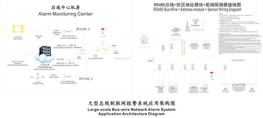
Bus-Wiring Essentials: The Foundation for Scalable Alarms
Bus-wiring flips the script on traditional designs by creating a shared highway for power and data, allowing devices to tap in along the line rather than radiating from a hub.
Core Principles of Bus Architectures in Alarms
In intrusion systems, a bus typically comprises two to four conductors: +V, GND, and data pairs (e.g., RS-485 for addressable protocols). Devices “daisy-chain” along the trunk, with end-of-line terminators preventing reflections.
Advantages over star:
- Reduced Material Costs: One trunk versus dozens of home runs cuts copper by 60-80%.
- Flexibility: Add devices without rewiring the core.
- Resilience: Distributed topology minimizes single-point vulnerabilities.
For large villas, buses snake through central corridors; in factories, they follow overhead trays, adapting to zoning.
Protocols and Compatibility
Common buses include Honeywell’s V-Plex, DSC’s Combus, or open standards like Modbus. Ensure your panel supports hybrid modes for seamless integration with hardwired zones.
Crafting Hybrid Systems: Merging Bus Strength with Hardwired Reliability
Hybrid alarm panel wiring marries bus efficiency for long hauls with star clusters for local density, ideal for retrofits or mixed tech stacks.
Why Hybrids Excel in Complex Environments
In a villa with heritage wiring, retain star zones in core areas while extending buses to remote pools or guesthouses. Factories benefit by clustering high-risk machines on local stars fed by bus trunks, curbing attenuation.
Step-by-Step Design Process for Hybrids
- Map Electrical Zones: Divide the site into segments based on distance (e.g., <100m clusters) and risk (e.g., perimeter vs. interior). Use CAD tools like AutoCAD Electrical for visuals.
- Select Backbone: Opt for shielded 18 AWG multi-conductor cable for buses, rated for outdoor if needed (UV-resistant jackets).
- Integrate Expanders: Place bus-to-zone expanders (e.g., 8-input modules) at segment hubs. Wire local stars with 22 AWG for short drops (<50m).
- Balance Loads: Cap each bus segment at 0.5-1A; use current meters during planning.
- Test Interoperability: Simulate with bench setups—connect hybrid nodes and verify polling times under load.
- Document Schematics: Create layered diagrams showing bus trunks, star branches, and power injections.
This approach has proven transformative in deployments where full bus overhauls were cost-prohibitive.

Strategic Mastery: Deploying Repeaters and Isolators to Fortify Your Bus
In systems with dozens of detectors, a single fault can cascade like wildfire. Enter repeaters and isolators—your sentinels against collapse.
Repeaters: Boosting Signals and Power Over Distance
Repeaters regenerate voltage and retime data, extending buses beyond native limits (often 1-2km).
When and Where to Deploy Repeaters
- Thresholds: Install every 200-300m or after 20-30 devices, whichever hits first.
- High-Density Zones: Before clusters of motion sensors or door contacts pulling extra current.
- Environmental Hotspots: In areas prone to EMI, like near generators.
Detailed Installation Steps
- Site Survey: Measure existing drops with a scope; identify weak points.
- Select Model: Choose panel-compatible repeaters (e.g., with opto-isolated inputs for noise rejection).
- Mount Securely: Enclose in NEMA-rated boxes, elevated from floors.
- Wire In-Line: Cut the bus trunk, connect repeater inputs to upstream, outputs to downstream. Use crimp terminals for reliability.
- Power Locally: Feed from a dedicated 12V supply to avoid loading the main bus.
- Terminate Properly: Add 120Ω resistors if the repeater doesn’t include them.
- Commission: Test signal strength pre/post-repeater using protocol analyzers; simulate faults to confirm regeneration.
- Label and Map: Tag as “Repeater Node 1” with voltage readings noted.
In a factory setup with 40 detectors across 500m, strategic repeaters dropped fault rates from 15% to under 1%.
Isolators: Quarantining Faults for Uninterrupted Operation
Isolators segment the bus electrically, containing shorts or surges to one zone.
Strategic Placement Tactics
- Per Functional Area: One per building wing or production line, not arbitrarily by floor.
- Fault-Prone Spots: After outdoor segments exposed to weather or vandalism.
- Load Balancing: Pair with repeaters in high-device counts to prevent overload propagation.
Step-by-Step Implementation
- Risk Assessment: Analyze historical faults; prioritize isolators in vulnerable runs.
- Choose Type: Galvanic isolators for full separation, or fuse-based for cost savings.
- Integrate into Bus: Insert mid-trunk; connect via screw terminals, ensuring polarity.
- Test Isolation: Induce a short on one side; verify the other remains operational.
- Monitor Integration: Wire to panel inputs for fault alerts.
- Maintenance Protocol: Schedule quarterly checks for LED indicators and continuity.
- Documentation: Include in as-built drawings with isolation thresholds.
This “divide and conquer” method ensures a single wet sensor doesn’t doom the entire perimeter.

The Redundancy Art: Sculpting Backup Power Wiring for Enduring Resilience
When mains power cuts, alarms must persist—yet centralized batteries often falter in large scales due to extended drops.
Principles of Redundant Power Design
Embrace distributed redundancy: Local power nodes supplement the central supply, creating a web of failover paths.
Benefits in Action
- Stable Edge Delivery: Far-end modules get fresh volts, bypassing long-run losses.
- Extended Runtime: Segmented batteries last longer under load.
- Fault Tolerance: One failed pack doesn’t blackout the system.
Expert Techniques for Wiring Redundancy
- Distributed Battery Placement: Install sealed lead-acid or lithium packs at expander hubs, sized for 24-48 hours (e.g., 7Ah per 10 devices).
- Supervised Charging: Use panel-monitored chargers; wire via diodes to prevent backfeed.
- Automatic Switching: Employ relays or MOSFET switches for seamless mains-to-battery transition.
- Grounding Mastery: Separate power grounds from signal to avoid loops; use star grounding at panels.
- Cable Sizing for Backups: Upsize to 16 AWG for battery runs to minimize sag during discharge.
- Redundant Paths: Dual-wire critical segments with auto-failover switches.
- Testing Regimen: Simulate outages; measure endpoint volts and runtime.
In a villa deployment amid frequent storms, this setup maintained 100% uptime during 12-hour blackouts.
Hands-On Implementation: Wiring Your Hybrid Bus System from Scratch
Ready to build? Here’s a comprehensive guide, assuming a 300m factory with 50 detectors.
Preparation Phase
- Gather Materials: 18 AWG shielded cable for bus, 22 AWG for locals; expanders, repeaters, isolators; tools (crimpers, multimeter, labeler).
- Safety First: De-energize areas; wear PPE; comply with NEC/IEC codes.
Wiring Steps
- Lay the Bus Trunk: Route from panel through conduits; avoid sharp bends.
- Connect Panel: Wire +V/GND/data to bus outputs; install fuse protection.
- Add Devices: Daisy-chain detectors with short spurs (<20m); address each per protocol.
- Insert Repeaters/Isolators: As mapped, every 200m.
- Local Stars: From expanders, radiate to clusters; use EOL resistors.
- Power Injections: At midpoints, add auxiliary PSUs paralleled via diodes.
- Backup Integration: Wire batteries in parallel with mains, supervised.
- Termination: End trunks with matching impedances.
Commissioning and Verification
- Power-Up Sequentially: Segment by segment, check volts (aim >11V).
- Load Test: Activate all devices; monitor drops.
- Fault Simulation: Short zones; confirm isolation.
- Documentation: Photograph junctions; create handover manual.
Troubleshooting Mastery: Nipping Issues in the Bud
Even bulletproof designs need vigilance. Common woes:
- Intermittent Drops: Check connections; upgrade to thicker wire.
- Noise-Induced Faults: Shield cables; reroute from EMI sources.
- Backup Failures: Test batteries annually; replace if capacity <80%.
Pro Tip: Invest in network analyzers for bus health scans.
Real-World Case Studies: Lessons from the Field
Case 1: Villa Overhaul in Coastal Terrain
A 10,000m² estate plagued by saltwater corrosion. Hybrid bus with isolators every 100m and redundant batteries cut faults by 90%, extending MTBF to 5 years.
Case 2: Factory Expansion in Industrial Park
Scaling from 20 to 80 detectors across 400m. Voltage model guided 16 AWG upgrades; repeaters ensured zero attenuation, slashing maintenance calls.
These showcase how targeted wiring turns vulnerabilities into victories.
Sourcing Savvy: What Bulk Buyers Demand from Vendors
As a procurement leader, insist on:
- Detailed specs for bus limits and drop tolerances.
- Hybrid-compatible panels with built-in diagnostics.
- Warranties covering wiring-induced failures.
- Training resources for installers.
Top brands like Bosch or Paradox excel here—vet them rigorously.
Wrapping Up: Empower Your Alarms with Wiring Wisdom
Mastering alarm panel wiring in bus-hybrid systems isn’t optional—it’s essential for conquering the chaos of large-scale deployments. By slashing voltage drops, isolating threats, and weaving redundant power, you build defenses that stand vigilant. For your next project, apply these tactics to deliver unyielding security. Ready to discuss custom solutions or explore our suite of alarm innovations? Reach out—let’s fortify your world together.