

As a senior technician with more than 25 years installing, commissioning, and troubleshooting network alarm systems across banks, chain stores, industrial parks, and residential communities, I have seen the same heartbreaking pattern repeat itself on hundreds of job sites. A shiny new network alarm system is deployed with high hopes—only for false alarms to flood the monitoring center, response times to stretch into minutes instead of seconds, connections to drop without warning, and misconfigurations to turn a sophisticated anti-theft solution into an expensive paperweight.
These failures are not random. They stem from the gap between laboratory promises and the unforgiving realities of real-world deployments: unstable networks, environmental interference, human error, and shortcuts taken during installation. The cost is staggering—fines from police departments, eroded trust with clients, wasted engineer hours, and, worst of all, genuine security breaches that slip through because the system cried wolf too many times.
In this in-depth guide, we break down the four most common reasons network alarm systems fail in the field—false alarms, transmission delays, disconnections, and misconfigurations—and deliver battle-tested, step-by-step fixes that professional installers and system integrators can implement immediately. Whether you are an engineering contractor, an alarm installer, or a procurement manager sourcing bulk network alarm solutions, this article will give you the practical playbook to turn unreliable installations into rock-solid anti-theft fortifications.
By the end, you will understand exactly why most network alarm systems underperform and, more importantly, how to make yours the exception that delivers reliable protection every single day.
Understanding Network Alarm Systems: The Promise Versus the Reality
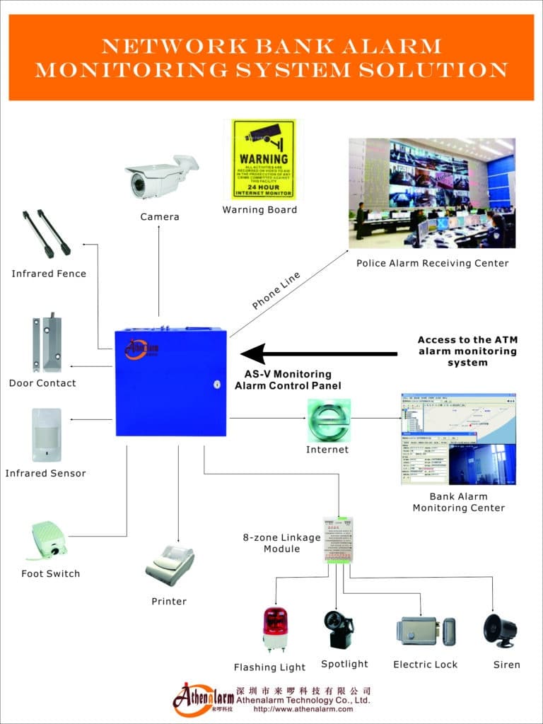
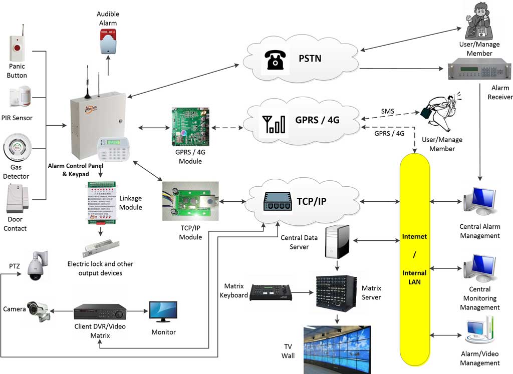
A network alarm system—often called a network alarm or IP-based alarm panel—transmits intrusion, fire, or panic signals over TCP/IP, 4G/5G, or hybrid networks to a central monitoring station. Unlike traditional PSTN or radio systems, it offers faster data rates, video linkage, remote diagnostics, and integration with CCTV, access control, and smart sensors.
The promise is compelling: real-time alerts, automatic video pop-ups on alarm events, centralized management of hundreds of sites, and lower long-term communication costs. Yet in practice, many systems fail to live up to this because the focus during sales and initial design stays on features rather than deployment resilience.
A fully functional network alarm ecosystem typically consists of the following layers working in concert:
- Field devices: PIR motion sensors, door and window contacts, glass-break detectors, panic buttons, smoke and gas detectors, vibration sensors, and perimeter beams.
- The alarm control panel: The brain of the system. It collects zone status in real time, applies arming and disarming logic, manages partitions, and forwards events upstream.
- Communication path: Primary TCP/IP over LAN/WAN, with 4G/5G cellular as the backup path. Both must be active and supervised simultaneously.
- Monitoring center software: Receives encoded alarm signals, decodes account numbers and event codes, and dispatches responses. Incompatibility between panel encoding and receiver decoding is a very common source of silent failures.
- Video integration layer: IP cameras linked to alarm zones so that every event triggers automatic live-view pop-up and pre-alarm recording at the monitoring station.
- Remote management platform: Centralised software that allows engineers to monitor panel health, push firmware updates, and pull event logs without on-site visits.
From my experience commissioning AS-9000 series panels and similar TCP/IP/4G control panels across dozens of vertical markets, the most successful installations treat the network alarm not as a standalone gadget but as a tightly integrated anti-theft ecosystem. When any one of those layers is missing, poorly specified, or incorrectly configured, the four failure modes we are about to dissect become not just possible—they become inevitable.
Understanding this layered architecture is the single most important mindset shift an installer can make. Every troubleshooting call I have ever attended traces back to a problem at one of those six layers. Fix the layer, and you fix the system.
Failure Mode 1: False Alarms – The Silent Killer of Credibility
False alarms represent 80–99% of all security system activations in many jurisdictions. For network alarm systems, the problem is amplified because digital signals travel instantly, triggering immediate—and expensive—responses. A single site generating more than three false alarms per month will typically be flagged by the monitoring center; generate more than five and many police authorities will suspend priority response entirely.
Root Causes in Real Deployments
1. Environmental Interference and Poor Sensor Placement
Motion detectors placed near HVAC vents, windows with direct sunlight, or outdoor perimeters exposed to wind, rain, or animals trigger repeatedly. In one chain-store project I audited, 47 false alarms in a single month were traced to a PIR sensor aimed at a swinging glass door that caught reflections from passing cars. Similar issues arise from fluorescent lights cycling on and off near detectors, ceiling fans creating air turbulence, and large animals—including domestic pets—moving through coverage zones at night.
Outdoor passive infrared detectors are particularly vulnerable. Temperature differentials between an animal’s body heat and the ambient environment can easily exceed the detection threshold, especially in cooler climates. Wall-mount height, detection angle, and lens mask configuration all matter enormously and are frequently skipped during rushed installations.
2. Improper Zoning and Sensitivity Settings
Installers often default to “one zone per floor” without subdividing high-risk areas. A single mis-zoned window contact can cascade into a full-site alarm. Equally problematic is leaving sensitivity dials at factory default: most PIR sensors ship at maximum sensitivity, which is appropriate for a forensics lab, not a live retail store.
Zone programming also affects how alarms escalate. If a zone is programmed as “instant” when it should be “entry/exit delayed,” every arming sequence where staff still need to exit through that point will trigger a false alarm. This is an extremely common error on first-time panel configurations.
3. User Error and Inadequate Training
Employees forget to disarm before opening doors, or they arm the system while cleaners are still inside. Studies consistently show human error accounts for the majority of false activations. In multi-tenant buildings or hotels, the problem compounds when different staff members have different arming habits and no standardised procedure exists.
A factor often overlooked is the keypad response time. If the entry delay is set shorter than it takes an average user to walk from the door to the keypad and enter their code, false alarms are structurally guaranteed—no amount of user training will prevent them.
4. Aging Hardware and Lack of Maintenance
Dust inside detectors, low batteries in wireless zones, or outdated firmware cause intermittent triggers that the network alarm dutifully reports. A passive infrared detector operating with a lens covered by 18 months of accumulated dust in a factory environment can produce wildly erratic behaviour that looks identical to an intrusion attempt in the event log.
5. Incorrect Wiring and Termination Resistance Errors
This cause is frequently missed in field diagnoses. Hardwired zone loops require a specific end-of-line (EOL) resistor value—typically 2.2 kΩ or 4.7 kΩ depending on the panel—to distinguish open-circuit (alarm), short-circuit (tamper), and normal (secured) states. Using the wrong resistor value, placing it at the panel instead of at the detector, or missing it entirely causes zones to behave unpredictably. I have resolved false-alarm complaints at three separate sites that turned out to have nothing wrong with the sensors whatsoever—only incorrectly valued EOL resistors installed by a junior technician.
The Real-World Impact
Repeated false alarms lead to police non-response policies, municipal fines that can reach thousands of dollars per year, and frustrated clients who eventually disable the entire network alarm system. For installers, it destroys repeat business and referral rates. In the most serious cases, a client who disables their alarm following excessive false activations then suffers an actual burglary—and the liability questions that follow can be career-ending.
How to Fix False Alarms – Step-by-Step Action Plan
Step 1: Conduct a Professional Site Survey Before Installation
- Map every proposed sensor location against environmental factors: airflow sources, heat emitters, reflective surfaces, natural light angles at different times of day, and expected foot traffic patterns.
- Use a laser measure and light meter to verify PIR coverage angles and confirm there are no reflective surfaces within the detection cone.
- Walk the site at the same time of day the system will typically be armed. Lighting conditions, HVAC cycle states, and building occupancy all change throughout the day.
- Test for electromagnetic interference with a spectrum analyzer if the site is near heavy machinery, inverters, or radio transmitters. Even nearby LED driver switching frequencies can interfere with poorly shielded detectors.
- Check for animals: ask the client directly whether rodents, birds, or domestic pets have access to any monitored area after hours.
Step 2: Select the Right Detector for Each Zone
Not every zone requires the same sensor technology. Match detector type to environment:
- Standard interior zones: Dual-technology PIR + microwave detectors. These require both technologies to trigger simultaneously, dramatically reducing environmentally-caused false alarms.
- High-traffic retail entries: PIR curtain sensors with a narrow vertical detection beam rather than a wide-angle lens, combined with an entry delay long enough for staff to reach the keypad.
- Perimeter and outdoor zones: Active infrared beam detectors or microwave barriers with adjustable sensitivity, plus anti-masking capability to detect spray or obstruction attacks.
- Windows and glass partitions: Dedicated acoustic glass-break detectors calibrated to the specific glass type and thickness, never a wide-angle PIR aimed at a glass surface.
- Server rooms and vaults: Dual-technology with vibration sensing and contact switches on every access point, giving multiple independent confirmation layers before an alarm is reported.

Step 3: Implement Video Verification
Integrate the network alarm with CCTV so that every alarm event automatically triggers a live video pop-up and a 10-second pre-alarm recording at the monitoring station. This single upgrade can reduce verified false-alarm dispatches by over 70%. The monitoring operator can visually confirm whether movement is a person, an animal, or an environmental artifact before generating any response. Without video verification, every alarm must be treated as real—which is both expensive and operationally unsustainable.
For video verification to work reliably, the camera resolution at the relevant zone must be sufficient to clearly distinguish a human figure. A 2MP camera at the right angle and distance is worth more than a 4K camera aimed incorrectly.
Step 4: Proper Zoning and Programming
- Assign each high-risk entry point its own dedicated zone with entry and exit delays tailored to that specific door type and the realistic time a user needs to reach the keypad. Measure this physically—have a staff member walk through the process and time it.
- Enable swinger suppression (sometimes called alarm limit or zone bypass after multiple activations). This limits repeated reports from the same zone within a configurable short window, preventing a chattering contact or fluctuating sensor from flooding the monitoring center.
- Set sensitivity levels individually based on zone environment: approximately 75% for controlled interior corridors, 40–50% for areas with airflow or reflective surfaces, and use manufacturer-recommended settings as a starting floor rather than a final configuration.
- Verify EOL resistor values against the panel specification sheet before wiring. Place the resistor at the detector end of the loop, not at the panel.
- Use the panel’s zone walk-test function and watch the event log in real time. Every zone should produce exactly one clean trigger per deliberate activation and zero triggers at rest for a full 10-minute monitoring period.
Step 5: User Training and Arming Procedures
- Create laminated quick-reference cards at every keypad: arm sequence, disarm sequence, emergency code, and who to call for assistance. Make the font large enough to read under stress.
- Schedule mandatory training sessions at commissioning and quarterly thereafter. Record attendance.
- Use the network alarm’s mobile app to send push notifications 30 seconds before automatic arming, giving staff time to exit or abort.
- Assign individual user codes to every staff member who arms or disarms. This creates an accountable audit trail and allows you to identify which user is consistently generating false activations.
- Set entry delays to a minimum of 30 seconds for most sites. Test it physically with the actual users—not the installer—before finalising.
Step 6: Scheduled Maintenance Protocol
- Every 6 months: clean detector lenses with a soft brush and compressed air, test battery voltage on all wireless devices, update firmware on the panel and any network modules.
- Log every false alarm with a root-cause analysis entry in your service ticket system. Track trends: three false alarms from the same zone in the same month is a pattern requiring physical investigation, not just a remote acknowledgement.
- After any building renovation, HVAC change, or furniture rearrangement in a monitored area, re-survey and re-test every affected zone. Environmental conditions change constantly.
When I applied this exact protocol to a 28-store retail chain, false alarms dropped from 312 per quarter to 19. The monitoring center finally trusted the system, police response times improved dramatically, and the client renewed their monitoring contract for a further three years.
Failure Mode 2: Transmission Delays – When Seconds Feel Like Minutes
Network alarm systems are marketed as “instant,” yet many installations experience 15–90 second delays between event detection at the sensor and signal receipt at the monitoring center. In a smash-and-grab burglary, the window of opportunity is often under 60 seconds. Those delays are not a minor inconvenience—they are the difference between prevention and loss.
Primary Causes of Transmission Delay
Network Latency and Congestion
Shared office Wi-Fi or consumer-grade routers introduce unpredictable jitter. Packet loss on 4G during peak hours compounds the issue. In open-plan offices with dozens of concurrent users streaming video or performing large file transfers, an alarm panel sharing the same LAN without traffic prioritisation can wait multiple seconds just to get a packet through the router queue.
Incorrect Communication Protocol Settings
Using UDP instead of TCP for critical alarm signal transport means packets can be dropped with no retransmission. TCP guarantees delivery but adds handshake overhead—the key is configuring the panel to use TCP for event reporting and enabling heartbeat polling so that connection state is continuously verified. Failing to configure heartbeat allows a silently failed connection to go undetected for hours.
Firewall and Port-Blocking Issues
Corporate IT departments routinely block outbound ports that alarm panels require. The commonly used port ranges—80, 443, and proprietary ranges typically between 10000 and 12000—are often blocked by default in enterprise firewall rule sets. ISP-level Carrier-Grade NAT (CG-NAT) creates an additional layer of complication by preventing the monitoring server from initiating a direct inbound connection to the panel. This is an especially frequent issue on business broadband and mobile data connections in urban areas.
Cloud Platform Overload or Poor Server Routing
Some low-cost network alarm platforms route signals through distant servers, adding unnecessary network hops and geographic latency. A panel in Southeast Asia routing through a server in Europe introduces 200–400 ms of baseline latency before any processing has occurred—and under cloud server load spikes, this can climb further.
Panel-Side Software Delays
Some older firmware implementations have a built-in “confirmation delay” that waits for multiple zone activations before transmitting, intended to reduce false alarms but actually introducing a hard-coded reporting delay of 10–30 seconds. Always check the panel firmware release notes for any default confirmation timer settings and disable or minimise them unless specifically required by the site risk profile.
Practical Fixes for Sub-5-Second Delivery
Step 1: Choose Dual-Path Communication From the Start
Configure every panel for primary TCP/IP over the site LAN or WAN, with a secondary 4G/5G SIM as an independent backup path. Enable automatic failover with a switchover time of under 3 seconds. The key word is “independent”—the cellular module must have its own antenna and SIM card, completely separate from the primary IP path. If both paths share a router and that router reboots, neither path is available. True redundancy means two physically separate communication routes.
Step 2: Optimise Network Settings on the Alarm Panel
- Assign the alarm panel a static IP address rather than relying on DHCP. A DHCP lease expiry that the panel does not handle gracefully can cause a communication outage that nobody notices until an alarm fails to arrive.
- Enter DNS server addresses manually. Use a reliable public DNS (such as 8.8.8.8 and 8.8.4.4 as secondary) in addition to the local DNS server.
- Enable QoS (Quality of Service) prioritisation on the router for alarm panel traffic. Mark the panel’s traffic with DSCP 46 (Expedited Forwarding class), which gives it priority over regular LAN traffic in every queue management algorithm. This single setting eliminates congestion-related delays in the majority of shared-network deployments.
- Place security devices on a dedicated VLAN, isolated from general office or guest traffic. This removes them from the broadcast domain of high-traffic segments and makes firewall rule management straightforward.
- Ensure the router is business-grade with a proper stateful firewall, not a consumer device. Consumer routers regularly drop established TCP connections during NAT table housekeeping cycles, which silently kills alarm panel communication.
Step 3: Configure Heartbeat and Supervisory Polling
Set the panel to send a supervisory heartbeat signal to the monitoring receiver every 30–60 seconds. Program the receiver to generate a “communication trouble” alert if three consecutive heartbeats are missed. This ensures that a failed connection is detected and reported within 90–180 seconds at most, rather than discovered only when an alarm fails to arrive during an actual incident.
On the panel side, also configure a “communication fault” output that can trigger a local alert or relay—useful on sites where an on-site guard needs to know immediately that remote connectivity has been lost.
Step 4: Test End-to-End Latency Before Handover
- Use the panel’s built-in test transmission function and measure the time from trigger to receipt at the monitoring center. Document the result.
- Run a manual ping and traceroute from a laptop on the same network segment as the panel to the monitoring server IP. More than 200 ms round-trip under no-load conditions indicates a routing problem that needs resolving before commissioning.
- Simulate peak-load conditions by running large file transfers on the LAN simultaneously with test transmissions. If latency degrades significantly, the QoS configuration needs adjustment.
- Test cellular failover: physically disconnect the Ethernet cable and confirm the panel switches to 4G within the specified time and that the monitoring center receives a “primary path failure” event followed by continued signal delivery via the backup path.
Step 5: Deploy Edge Alarm Receivers for Large Multi-Site Campuses
For industrial parks, hospital campuses, or university estates where dozens of panels report to a single monitoring point, install a local alarm receiver on the site network that aggregates and verifies events locally before forwarding only confirmed alarms to the cloud. This architecture reduces the round-trip communication path to a LAN hop (sub-millisecond) for event aggregation and then uses a stable WAN connection for confirmed event forwarding. It also means the entire site continues operating normally even if the internet connection to the cloud platform is temporarily degraded.
In a hospital deployment I handled, switching to dual-path communication with proper QoS and a local receiver reduced average alert delivery time from 47 seconds to under 4 seconds—a result that directly improved emergency response capability for staff duress alarms.
Failure Mode 3: Disconnections and Downtime – The Invisible Breakdown
Nothing undermines confidence in a network alarm system faster than discovering it has been “offline” for an unknown period with no alert generated. Monitoring centers receive a “communication failure” event, but by then the system has already been dark for some time. The root cause is frequently elusive and can take days to diagnose without the right approach.

Common Triggers for Disconnections
Power Supply Instability
Voltage sags, brownouts, and brief power interruptions—even those lasting only a few cycles—can reboot an alarm panel that is not protected by a proper UPS. Many installations use the panel’s built-in battery backup as the primary power redundancy measure, which is sufficient for extended outages but provides zero protection against fast voltage transients that cause an immediate hardware reset without triggering low-battery monitoring.
Router and ISP Outages
Consumer and entry-level business routers restart their WAN connection daily or after firmware updates, often at scheduled maintenance windows in the early hours of the morning. If the alarm panel’s TCP/IP stack does not detect the dropped connection and automatically re-establish it, the system silently loses communication without generating any fault event. This is a firmware-level issue that varies between panel manufacturers and should be explicitly tested during commissioning.
Firmware Bugs in the TCP/IP Stack
Some panel firmware versions have known bugs where the TCP/IP connection handler allocates memory and never releases it, eventually causing the network stack to lock up after days or weeks of continuous operation. The panel itself continues to function locally—zones arm and disarm, sirens trigger—but no events reach the monitoring center. This class of failure is insidious because everything looks normal at the site. Only the monitoring center notices the missing heartbeats. Always check manufacturer firmware changelogs for network stack stability fixes before deploying a firmware version at scale.
Physical Infrastructure Damage
Ethernet cables in exposed locations get damaged by rodents, moisture ingress, or mechanical stress during building maintenance. Outdoor 4G antennas suffer lightning strike damage, connector corrosion, or cable sheath breakdown. Internal antenna cables inside panels can come loose during vibration—particularly in industrial environments with heavy machinery nearby.
SIM Card and Cellular Network Issues
4G SIM cards can be deactivated by carriers for non-use if the data plan requires a minimum monthly consumption. Some M2M data plans have traffic thresholds that trigger throttling or suspension. SIM cards also have a physical service life and can fail. These are failures that manifest as “cellular backup unavailable” at exactly the moment it is most needed.
Bulletproof Reliability Fixes
Step 1: Implement Redundant and Conditioned Power
- Connect the alarm panel—and its associated router and PoE switch—to a dedicated UPS with at least 4 hours of runtime at full load. Size the UPS based on actual measured current draw, not panel manufacturer ratings, which are often conservative.
- Use a UPS with automatic voltage regulation (AVR) rather than a standby-only UPS. AVR continuously corrects voltage fluctuations without switching to battery, protecting against brownouts that a standby UPS would not even detect as an event worth responding to.
- Enable low-battery supervision reporting on the panel so that the monitoring center receives a notification as the UPS battery degrades below a threshold—before it fails entirely during an actual power outage.
- Include the router, managed switch, and any PoE injectors on the same UPS circuit. A panel with perfect battery backup that loses its router has no more communication than an unpowered panel.
Step 2: Enable Automatic Network Recovery
- Program the panel to automatically reboot its network module after three consecutive missed heartbeat cycles. Most modern panels support this in the network settings menu under a “connection watchdog” or equivalent parameter.
- Use a watchdog timer at the hardware level if the panel supports it. A hardware watchdog resets the network processor regardless of software state, resolving firmware memory leak issues that a software watchdog cannot catch.
- Configure the router to monitor the panel’s IP with periodic pings and automatically restart the WAN connection if connectivity to a known external address (such as 8.8.8.8) is lost. Some business-grade routers support this as a built-in “WAN failover and recovery” feature.
Step 3: Deploy Cellular as a Genuinely Independent Backup
The cellular backup path is only useful if it is truly independent from the primary path. This means a dedicated 4G module with its own external antenna, its own SIM card on a separate carrier from the organisation’s primary internet service, and independent routing that does not pass through the same router as the LAN connection.
- Mount the external 4G antenna as high as practical and in the clear—building materials attenuate 4G signals significantly, and an internal antenna in a metal panel enclosure may have 10–15 dB less effective gain than an external directional antenna.
- Test the cellular signal level in the panel’s diagnostic menu before commissioning. Aim for at minimum -85 dBm RSSI at the installation location. Below -95 dBm, connection reliability becomes marginal.
- Verify that the SIM data plan is M2M/IoT rated with no minimum usage deactivation clause, and set up a calendar reminder to check SIM account status quarterly.
Step 4: Remote Diagnostics and Proactive Monitoring
- Use the central management software to monitor signal strength, packet loss percentage, and panel uptime across all managed sites in real time. Any device dropping below 95% connectivity over a 24-hour rolling window should generate an automatic work order for investigation.
- Configure the monitoring platform to send daily health summary reports by email or messaging app. A site that has been at 100% uptime for 30 days and then drops to 87% is showing an early-stage failure—catching it before it reaches 0% is the goal.
- Implement remote firmware update capability. Being able to push a firmware fix to 50 panels overnight from a central console—rather than dispatching engineers to each site—is not just convenient, it is operationally essential for maintaining consistent software versions across a large fleet.
Step 5: Cable, Connector, and Antenna Best Practices
- Use shielded Cat6 or better for all Ethernet runs, terminated with properly crimped connectors rather than punch-down keystones where possible. In industrial environments, use Cat6A in conduit.
- Keep Ethernet runs under 90 meters between active devices to allow margin within the 100-meter specification. For longer runs, use a managed PoE extender or switch mid-run rather than exceeding the cable length limit.
- Apply weatherproofing self-amalgamating tape to all outdoor antenna connector joints. Connector corrosion is the leading cause of 4G antenna performance degradation in humid or coastal environments.
- Install surge protection on the Ethernet port of every panel located near building entry points or in areas with high lightning strike risk. Surge events on data lines are underestimated as a panel-killer.
After retrofitting 15 bank branches with this complete reliability package, communication trouble tickets fell by 92% over 18 months. Not one site experienced an undetected communication failure during that period.
Failure Mode 4: Misconfigurations – The Most Preventable (and Most Common) Disaster
Misconfigurations are the leading cause of “it worked in the lab but failed on site” complaints. Network alarm panels are sophisticated embedded computers, and a single incorrect parameter can silently break communication while leaving the rest of the system appearing functional. The particularly dangerous aspect of misconfiguration failures is that they often go undetected until a real alarm event fails to arrive—which is the worst possible moment to discover the system is not working.
Frequent Mistakes Found in Field Audits
- Incorrect IP address, subnet mask, or gateway: A panel with a correct IP address but wrong subnet mask will appear to be online on the local network but will fail all external communications silently.
- Wrong port numbers or protocol selection: UDP instead of TCP for event reporting, or a port number that was changed by the monitoring center but not updated in the panel configuration.
- Missing or incorrect account codes: The monitoring center’s receiver software decodes account codes to identify which client and site generated an event. A transposed digit means every alarm from that panel arrives at the receiver as an “unknown account” that generates no response.
- Incorrect event code format: Different receivers use different encoding formats—Contact ID, SIA DC-09, or proprietary formats. A panel sending Contact ID to a receiver expecting SIA generates garbled events that are discarded or misinterpreted.
- Zone mapping errors between panel and monitoring software: Zone 1 on the panel must correspond to Zone 1 as defined in the monitoring center’s customer record. A mapping offset of just one zone number means every alarm is attributed to the wrong location, causing operators to check the wrong camera or dispatch responders to the wrong door.
- Incompatible firmware between panel and integration modules: CCTV integration, access control linkage, and smart sensor modules often have their own firmware that must be at a compatible version with the main panel. Mismatched firmware versions cause integration features to silently fail.
- Encryption mismatch: If AES encryption is enabled on the panel but not configured on the receiver—or vice versa—all communication fails. Since the failure mode is the same as a disconnection, this is often misdiagnosed as a network problem.
Step-by-Step Configuration Mastery
Pre-Installation Checklist (Complete Before Touching the Panel)
- Obtain all network parameters in writing from the client’s IT department: static IP address to be assigned to the panel, subnet mask, default gateway, primary and secondary DNS server addresses, VLAN ID if applicable, and confirmation of which ports will be opened on the firewall for alarm traffic.
- Obtain from the monitoring center in writing: their server IP address or domain name, port number, communication protocol (TCP preferred), encoding format (Contact ID, SIA DC-09, or other), account number format, and any encryption key if end-to-end encryption is required.
- Download the latest stable firmware version from the manufacturer and read the release notes before the installation date. Note any parameters that changed between firmware versions.
- Prepare a site-specific configuration template spreadsheet that will become the permanent configuration record for this site. Every parameter entered into the panel should be recorded in this document before, during, and after configuration.
- Confirm CCTV camera IP addresses, port numbers, and RTSP stream credentials if video integration is planned. Verify camera firmware compatibility with the alarm panel’s integration module.
Panel Programming Sequence (Follow This Order Every Time)
- Perform a factory reset of the panel to ensure no residual configuration from previous deployments or testing is present.
- Enter the installer code and access the system configuration menu.
- Set the date, time, and time zone. Incorrect timestamps corrupt event logs and make post-incident analysis useless.
- Navigate to the communication menu and select the appropriate mode—”Network + Cellular” for dual-path configurations.
- Input the static IP address, subnet mask, default gateway, and DNS server addresses exactly as provided by the IT department. Double-check each octet individually.
- Enter the monitoring center’s server IP address or FQDN and port number. Confirm the protocol selection matches the receiver’s expectation.
- Enter the unique account number and partition codes. Have a second person verify these against the monitoring center’s configuration record before saving.
- Configure the encoding format to match the receiver (Contact ID is the most universally supported format; use SIA DC-09 only when explicitly confirmed by the monitoring center).
- Enable AES-256 encryption if supported by both the panel and the receiver, and enter the same encryption key on both sides. Verify with the monitoring center that encryption is active and verified at their end before proceeding.
- Configure heartbeat interval (30–60 seconds) and the number of missed heartbeats before a communication fault is reported (3 is the standard).
- Save all communication settings and perform a manual test transmission. Confirm receipt at the monitoring center with the operator on the phone.
- Program zone types, entry/exit delays, and sensitivity settings as specified in the zone plan. Walk-test every zone.
- Configure user codes with appropriate access levels. Do not use the default installer code as a permanent user code.
- Export and save the full configuration file from the panel’s programming software. Store in the client file.
Integration with CCTV – The Deployment Game-Changer
Video verification is not optional for professional-grade network alarm deployments—it is the feature that separates a credible anti-theft system from a simple event logger. Proper integration requires:
- Mapping each alarm zone to one or more specific camera presets. When Zone 3 (rear warehouse door) activates, the monitoring software should automatically bring up the cameras covering the rear dock area—not the front reception camera.
- Configuring pre-alarm recording: most IP cameras support a ring buffer that retains 5–30 seconds of footage before any trigger event. Ensuring this pre-alarm clip is accessible to the monitoring operator means they can see what happened leading up to the alarm, not just the aftermath.
- Setting the video pop-up response time target at under 1 second from alarm receipt to live view display at the monitoring console. Anything longer is a configuration or network issue worth resolving.
- Testing video integration by triggering each zone manually and confirming the correct camera view appears at the monitoring center. Document each zone-to-camera mapping in the client file.
Post-Configuration Validation (The Step Most Often Skipped)
- Walk-test every zone individually while an observer monitors the receiver display. Confirm zone name, zone number, and account code match the expected values for each activation.
- Simulate a complete power failure: disconnect mains power and confirm the panel transitions to battery backup, continues reporting, and sends a “mains failure” event to the monitoring center.
- Simulate a network failure: disconnect the Ethernet cable and confirm the panel switches to cellular within the specified failover time and that the monitoring center receives a “primary path failure” event.
- Simulate a full power and network failure simultaneously: confirm the panel recovers correctly when both are restored and does not require manual intervention to resume normal operation.
- Perform a 72-hour burn-in monitoring period before formal handover. Review the event log for any unexpected zone activations, communication restarts, or error codes.
- Export the final configuration, sign the commissioning certificate, and provide the client with a system overview document that includes their account number, monitoring center contact details, and a brief description of what each zone covers.
Failure Mode 5: Cybersecurity Vulnerabilities – The Growing Threat Most Installers Ignore
This failure mode does not appear in most installer troubleshooting guides, but it is increasingly relevant as network alarm systems become IP-connected devices accessible from the public internet. A network alarm panel that is reachable via a default credential or an unpatched vulnerability is not just a malfunctioning system—it is an active security liability for your client.
Common Cybersecurity Weaknesses in Network Alarm Deployments
- Default credentials left unchanged: Many panels ship with well-known default installer codes (1234, 0000, or model-specific defaults that are publicly documented). Leaving these in place after commissioning is equivalent to leaving a spare key under the doormat.
- No encryption on remote access sessions: Remote programming via Telnet or unencrypted proprietary protocols exposes configuration data—including account codes, user codes, and server addresses—to anyone with network visibility.
- Panels directly exposed to the internet: Port-forwarding the alarm panel’s management port directly through the firewall to the public internet allows automated scanning tools to find and probe it within hours of exposure.
- Outdated firmware with known vulnerabilities: Manufacturers periodically release security patches. Panels running firmware versions that are multiple releases behind may have publicly disclosed vulnerabilities.
- Shared monitoring platform credentials: Multiple technicians using the same login to the central management platform means there is no audit trail for who made which configuration change.
Cybersecurity Hardening Steps
Step 1: Change All Default Credentials Immediately
Change the installer code, master user code, and any web interface or management software passwords immediately after the factory reset and before any network connection is established. Use strong, unique passwords—at minimum 10 characters with mixed case and digits. Record them in a password manager accessible to your team, not in a spreadsheet emailed to the client.
Step 2: Use VPN for All Remote Access
Never expose the panel’s management interface directly to the internet. Remote programming and diagnostics should always occur through a VPN tunnel terminated at the site router. Most business-grade routers support IPSec or OpenVPN site-to-site connections that can be pre-configured during on-site commissioning, allowing subsequent remote sessions to be fully encrypted without requiring on-site presence.
Step 3: Enable End-to-End Encryption on Event Reporting
Where the panel and monitoring receiver both support AES-256 encryption for alarm signal transport, always enable it. Unencrypted Contact ID signals transmitted over public IP networks can theoretically be intercepted and injected with spoofed events. Encryption eliminates this attack surface.
Step 4: Implement Multi-Factor Authentication on Management Platforms
The central management software that controls configuration across all managed sites is a high-value target. Any unauthorised access to this platform could theoretically allow an attacker to disarm systems, modify configurations, or delete event logs. Enable MFA on all management platform accounts and enforce it for every user.
Step 5: Establish a Firmware Update Policy
Monitor the manufacturer’s security advisories and firmware release channels. Establish a policy of reviewing new firmware within 30 days of release and deploying security patches within 90 days. Remote update capability makes this operationally feasible across large fleets without on-site visits.
Failure Mode 6: Poor System Design for Specific Vertical Markets
Generic network alarm configurations that work adequately in a standard retail store can fail systematically in specialised environments. Each vertical market has distinct physical, operational, and regulatory characteristics that must be reflected in the system design from the outset.
Bank and Financial Institution Deployments
Banks require alarm systems that meet specific regulatory standards in most jurisdictions—including mandatory dual-path communication, mandatory video linkage, defined response time requirements, and specific requirements around vault and ATM monitoring. A network alarm system deployed in a bank without meeting these standards is not just underperforming—it may be non-compliant and create regulatory liability for the client.
Key considerations specific to bank deployments include: hold-up (panic) button zoning that is separate from intrusion zones and treated with the highest priority; vibration detection on vault walls and floors that must remain sensitive enough to detect professional drilling equipment; ATM terminal monitoring that covers card skimmer installation attempts, not just forced entry; and communication redundancy requirements that typically mandate both IP and cellular paths active simultaneously with supervision intervals under 60 seconds.
Retail Chain and Multi-Site Deployments
Retail environments present high false-alarm rates due to customer traffic, delivery activity, and staff patterns that change daily. Effective retail network alarm design requires time-based zoning that automatically adjusts arming schedules to match opening hours, temporary zone bypass capability that is logged and time-limited rather than permanent, and integration with EAS (electronic article surveillance) systems at store exits to correlate tag activation events with alarm events.
Multi-site retail deployments also require centralised management capability: the ability to push arming schedule changes, firmware updates, and configuration modifications to hundreds of panels simultaneously. A retail chain with 200 stores cannot afford to send a technician to each site every time an opening-hours change affects arming schedules.
Industrial and Manufacturing Facilities
Industrial environments are electromagnetically hostile. Variable frequency drives, arc welding equipment, and high-current switching gear generate interference that can trigger false alarms on poorly shielded detectors or cause communication errors on cheaply constructed network modules. Sensor selection for industrial sites must prioritise interference immunity: use of shielded cable throughout, metal conduit where practical, and industrial-rated sensors with built-in noise filtering.
Industrial facilities also tend to have complex access patterns—shift workers arriving and departing at unusual hours, contractors with temporary access requirements, and areas that need to remain armed even while the broader facility is occupied. Multi-partition alarm panel design is essential in these environments to allow different areas to be independently armed and disarmed without affecting the overall system status.
Residential Communities and High-Rise Buildings
Community-scale network alarm deployments covering individual residential units within a larger complex present unique challenges around network architecture. Each residential unit ideally has its own panel (providing independent monitoring and accountability), but all units share the building’s network infrastructure. VLAN segmentation is critical to ensure that a network issue in one unit does not affect others, and that a technically capable resident cannot access or interfere with a neighbouring unit’s panel.
The management software must support hierarchical access control: the building management company can see status across all units, individual residents can see only their own unit, and the monitoring center has read-only event access across all units simultaneously. Configuring these permission tiers correctly at system setup is far easier than trying to retrofit them after residents have already been enrolled.
Advanced Best Practices for Bulletproof Network Alarm Deployments
Beyond addressing the six failure modes above, the installers who consistently deliver the most reliable network alarm deployments follow a set of additional professional disciplines that are worth detailing explicitly.
The 72-Hour Burn-In Test
Never formally hand over a commissioned network alarm system without running it for at least 72 hours under normal operational conditions while the event log is monitored by your team. The majority of firmware instability issues, intermittent connection drops, and environmental false alarms reveal themselves within the first 48–72 hours of operation. Discovering them before handover—rather than after—is the difference between a professional installation and a warranty callback.
During the burn-in period, specifically look for: any zone activation that occurs without a corresponding physical trigger, any communication restart events that do not have an obvious cause, any heartbeat timing that appears irregular, and any voltage readings on the panel’s power supply output that fall outside specification.
Managed PoE Switch Selection and Surge Protection
All IP cameras and network devices within the alarm ecosystem should be powered through a managed PoE switch rather than individual wall adapters. Managed switches provide per-port power monitoring (allowing detection of devices that are drawing abnormal current), remote port cycling capability (allowing a frozen camera or module to be rebooted remotely without on-site access), and VLAN configuration at the switch level for proper network segmentation.
Every PoE switch and panel power supply should have transient voltage surge suppression on both the mains input and data ports. Lightning-induced surges are one of the leading causes of network alarm panel hardware failure, and surge protection is dramatically cheaper than panel replacement.
Role-Based Access Control on Management Software
Central management platforms that control dozens or hundreds of panels need clearly defined user roles. At minimum: a read-only role for monitoring center operators who need event visibility but should not be able to change configurations; a site-level technician role that can configure and test panels assigned to their geographic territory but cannot access other regions; a senior engineer role with full configuration access but a mandatory audit log of every change made; and an administrator role for account and user management only, held by no more than two individuals.
Every configuration change on a production system should generate an audit log entry that records who made the change, when, and what the previous value was. This is not bureaucratic overhead—it is the fastest way to diagnose a misconfiguration introduced during routine maintenance.
Quarterly Remote Health Checks and Annual On-Site Audits
A network alarm system is not a “fit and forget” installation. Schedule quarterly remote health reviews where you pull event logs, check uptime statistics, review false-alarm frequency trends, verify backup path functionality, and confirm firmware versions. If any metric is outside acceptable parameters, generate a work order before the client notices a problem.
Once per year, conduct an on-site physical audit: clean all detectors, test every zone physically, verify all cable connections and termination resistances, test UPS battery condition under load, inspect antenna connections for corrosion, and perform a full walk-test with the monitoring center. Document the audit results and provide the client with a written health report. This annual service visit is also your most natural opportunity to identify system expansion needs and generate additional revenue.
Staying Current with Cybersecurity Threats
Subscribe to your panel manufacturer’s security advisory mailing list and to general ICS (industrial control system) security bulletins. Network alarm panels are embedded systems that share vulnerability classes with other networked devices—authentication bypass, buffer overflow, and insecure default configurations are all known categories of panel vulnerabilities that have been publicly disclosed across multiple manufacturers. Staying informed and acting promptly on advisories is part of your professional responsibility as an integrator.
Building a Pre-Deployment Quality Control Process
The most reliable way to prevent field failures is to catch them before the equipment leaves your workshop. Professional integrators who operate at scale implement a bench-testing and pre-configuration process that means every panel arriving on site is already configured, tested, and documented before the installation team touches a screwdriver.
Bench Testing Protocol
- Receive and inspect: Verify the firmware version on every panel received from stock before allocation to a project. If it is not the current stable release, update it in the workshop.
- Pre-configure from template: Apply the site-specific configuration template prepared during the pre-installation phase. Enter all network parameters, account codes, zone configurations, and user codes on the bench.
- Test all communication paths: Connect the bench panel to a test internet connection and a monitoring center test account. Confirm both IP and cellular paths transmit events correctly and that heartbeat supervision is functioning.
- Simulate fault conditions: Disconnect power, disconnect Ethernet, and combine both simultaneously. Verify the panel generates the correct fault events via the surviving path and recovers correctly when connections are restored.
- Document and label: Print a configuration summary label for the inside of the panel enclosure listing the account number, server IP, firmware version, and date of bench configuration. This information is invaluable for any future technician who opens the panel.
- Pack for dispatch: Include a printed copy of the full configuration record in the panel shipping box. If the panel is reconfigured on site, update the record and file it in the client folder.
This bench-testing process adds between one and two hours per panel but eliminates the majority of on-site troubleshooting time that stems from configuration errors discovered only after the panel is mounted on a wall in a difficult location.
Real-World Success Stories
Case 1: Regional Bank Chain – From Chaos to 99.98% Uptime
A regional bank with 22 branches was experiencing over 200 false alarms per month across the network and frequent 4G communication dropouts that were leaving individual branches dark for hours at a time without anyone noticing until the next morning’s health check. The monitoring center had begun treating alarms from this account with reduced urgency because of the false-alarm history—exactly the wrong outcome for a financial institution.
We conducted a full audit across all 22 sites over three weeks. The findings: 14 branches had PIR sensors placed within 1.5 metres of HVAC vents; 8 branches had incorrect EOL resistor values causing zone instability; all 22 branches were using the shared office LAN with no QoS configuration; and 11 branches had 4G antennas mounted inside metal enclosures with no external antenna, producing signal levels below -95 dBm.
After re-surveying sensor placements, correcting EOL resistors, implementing QoS and dedicated VLANs, installing external 4G antennas, adding video verification linked to the monitoring center, and conducting a full staff retraining session at each site, false alarms dropped to single digits per month across the entire chain within 60 days. Uptime reached 99.98% over the following 12 months. The monitoring center restored priority response status, and the bank extended the monitoring contract and added four new branches to the system.
Case 2: Large Manufacturing Plant – Eliminating Nightly Communication Failures
A manufacturing plant with 47 monitoring zones was experiencing nightly communication failures between 2:00 AM and 4:00 AM—consistently enough that the security manager had begun treating the overnight alarm reports as unreliable. Investigation revealed that the IT department’s network management system was performing a DHCP lease renewal process during those hours that was reassigning IP addresses to active devices, including the alarm panel, which was configured for DHCP rather than static IP. Each reassignment caused the panel’s connection to the monitoring center to drop. The panel’s firmware had a 15-minute reconnection timeout, meaning each DHCP renewal caused a 15-minute communication gap.
The fix took less than one day: assign a static IP address to the panel (reserved in the DHCP server to prevent address conflicts), configure a proper UPS for the panel and associated network hardware, and update the panel firmware to resolve the connection recovery timeout issue. Zero communication failures in the 14 months since the reconfiguration. The plant has since expanded the network alarm system to cover two additional warehouse areas.
Case 3: Hotel Chain – Managing Multi-Partition Complexity
A boutique hotel group managing six properties wanted a network alarm system that would allow the front desk of each property to arm and disarm guest room corridors independently of staff-only areas, while the monitoring center had full visibility across all properties simultaneously. Initial deployment by a previous contractor had resulted in a flat zone structure with no partitioning, meaning arming the system at the end of each night also armed occupied guest corridors—generating false alarms every time a guest returned late.
We redesigned the zone and partition structure at all six properties, creating separate partitions for guest areas (never armed while occupied), staff areas (armed on a schedule), and back-of-house areas (armed with a longer entry delay for overnight maintenance access). We configured role-based access in the management software so that each property’s front desk could control only their own partitions, while the group security manager had read-only oversight of all properties. False alarms dropped to zero within the first month, and the client has since added the network alarm integration to their property management system to automate arming based on check-in and check-out events.
These results are not anomalies. They are the predictable and repeatable outcome of applying systematic diagnostic and preventive disciplines to network alarm deployments.
Conclusion: Turn Failures Into Your Competitive Advantage
Network alarm systems do not have to fail in real-world deployments. Every failure mode described in this guide—false alarms, transmission delays, disconnections, misconfigurations, cybersecurity vulnerabilities, and poor vertical-market adaptation—is preventable with the right knowledge, the right equipment, and a disciplined installation process.
The difference between a chronic problem system and a flawless anti-theft installation is not luck or expensive hardware. It is rigorous pre-installation planning, systematic configuration, a thorough post-commissioning validation process, and a structured ongoing maintenance programme. These are not optional extras for premium clients—they are the baseline professional standard that every installer should apply to every deployment.
If you are an installer who is tired of chasing false-alarm callbacks, an engineering firm losing clients to more reliable competitors, or a procurement manager trying to source network alarm solutions that actually perform as specified in real-world conditions, the fixes in this guide will save you time, money, and professional reputation.
At Athenalarm, we have refined these exact principles into our AS-9000 series network alarm systems and AS-ALARM central management software. Our solutions are engineered from the ground up to address the failure modes that plague most deployed systems: dual-path communication with automatic failover, AES-encrypted event reporting, comprehensive remote diagnostics, video integration with pre-alarm recording, and multi-site centralised management built for professional integrators who manage large panel fleets.
Ready to deploy network alarm systems that perform reliably from day one? Contact our technical support team for a free site assessment, configuration review, or bulk quotation. Visit our network alarm system solutions page to learn more about the full product range—or reach out directly. We are here to help you protect what matters most.
Your next installation can be the one that sets the new industry standard. The knowledge is in this guide. The tools are ready. The only remaining variable is whether you choose to apply them.