
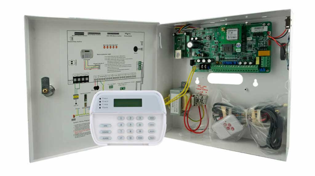
Introduction: Why Bus Topology Matters in Modern Alarm Systems
In modern intrusion alarm systems, bus topology design directly determines system stability, scalability, and long-term maintenance cost. For designers and engineers working with modular alarm platforms, selecting the right alarm bus topology is not a theoretical decision — it directly affects fault tolerance, communication reliability, and compliance with international security standards.
Among all wiring architectures, star and daisy-chain alarm wiring remain the two most widely adopted models in professional security installations. Each offers distinct advantages and limitations depending on system scale, environmental conditions, and risk profile.
This article provides a technical, experience-based explanation of how these topologies work, how to implement them correctly, and how to choose the most suitable option for real-world intrusion alarm projects.
Understanding Alarm Bus Topology in Modular Systems
An alarm bus topology defines how field devices—such as detectors, keypads, expanders, and I/O modules—communicate with the control panel using a shared communication medium.
Most modern modular alarm systems rely on:
- RS-485 (most common)
- CAN bus (in higher-end or industrial-grade systems)
- Proprietary multi-drop protocols based on differential signaling
These technologies enable multi-device communication over long distances, allowing system expansion without excessive cabling.
However, poor bus topology design is one of the most common root causes of:
- Intermittent device loss
- False alarms
- Communication timeouts
- System instability under load
Field data from professional integrators consistently shows that over 25–30% of alarm system faults originate from wiring topology or termination errors, not device failure.
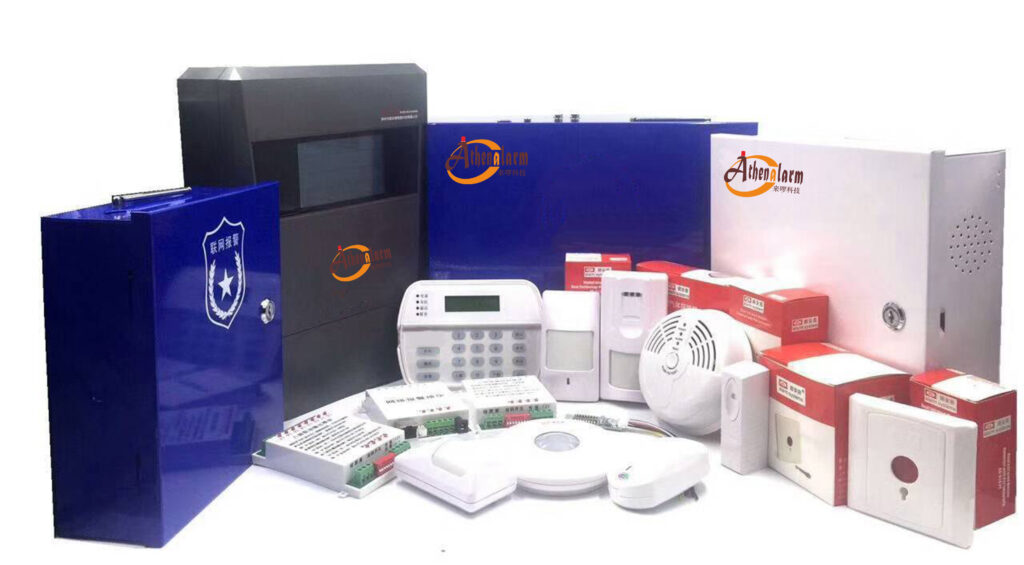
Daisy-Chain Alarm Wiring: Simple, Efficient, and Cost-Effective
Daisy-chain topology connects devices sequentially along a single communication path. Each device acts as a pass-through node, forming a continuous electrical chain from the control panel to the last module.
This approach is especially common in:
- Residential alarm systems
- Linear building layouts (corridors, perimeters, fences)
- Cost-sensitive installations
Key Advantages of Daisy-Chain Topology
1. Reduced Cable Length
Daisy-chain wiring typically reduces total cable usage by 20–40% compared to star layouts, lowering material and labor costs.
2. Clean Installation Path
Cabling follows a natural physical route, simplifying conduit planning and reducing installation time.
3. Compatibility with Standard Alarm Panels
Most intrusion panels supporting RS-485 are optimized for daisy-chain communication.
4. Scalable for Medium-Sized Systems
With proper termination, many systems support:
- Up to 1,200 m (≈ 4,000 ft) total bus length
- 64–128 devices per segment (manufacturer dependent)
Common Limitations and Risks
Despite its simplicity, daisy-chain wiring introduces several technical vulnerabilities:
- Single-point failure risk – A break or short affects all downstream devices
- Troubleshooting complexity – Fault isolation can be time-consuming
- Signal reflection risk – Improper termination causes communication instability
In electrically noisy environments (e.g., industrial sites), these weaknesses become more pronounced.
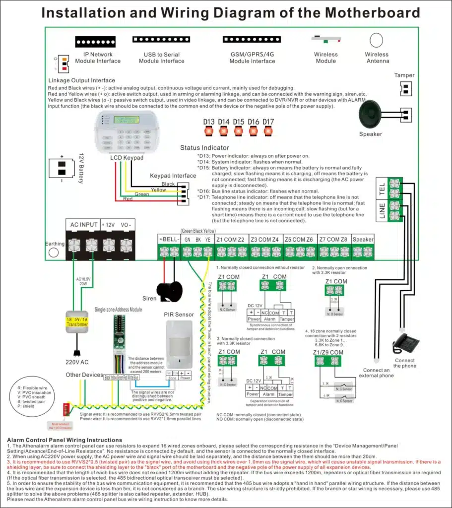
Step-by-Step: How to Wire a Daisy-Chain Alarm Bus Correctly
Even entry-level installers can achieve professional results by following these steps:
Step 1: Prepare Proper Cabling
Use shielded twisted-pair cable, typically:
- 22–18 AWG for data and power
- Drain wire connected to earth ground at one end only
Step 2: Connect the Control Panel
Wire the bus terminals:
- Data A (+)
- Data B (–)
- +12V
- GND
Ensure polarity consistency across all devices.
Step 3: Chain Devices Sequentially
At each module:
- Incoming wires land on input terminals
- Outgoing wires continue to the next device
Avoid star splits in a daisy-chain system.
Step 4: Terminate the Line
Install a 120-ohm termination resistor across Data A and Data B at the final device only.
Step 5: Test Communication
Use the panel’s diagnostic menu to:
- Confirm device addressing
- Check supervision status
- Identify voltage drops
This configuration aligns with EN 50131 Grade 2–3 requirements when properly supervised.
Star Topology: Maximum Stability and Fault Isolation
In a star topology, each device connects directly back to the control panel or to a centralized bus hub. Each branch operates independently.
This architecture is preferred in:
- High-security facilities
- Data centers
- Financial institutions
- Mission-critical infrastructure
Advantages of Star Wiring
1. Superior Fault Isolation
A cable fault affects only one device, not the entire system.
2. Higher Communication Stability
Shorter cable runs reduce noise, attenuation, and signal reflection.
3. Simplified Maintenance
Technicians can isolate faults quickly without interrupting other zones.
4. Easier Compliance with High-Security Standards
Star topology supports Grade 3–4 system designs under EN 50131.
Trade-Offs to Consider
- Increased cable consumption
- Higher installation labor
- Larger panel or expansion module requirements
However, for high-risk environments, these costs are often justified by improved uptime and reliability.
Practical Deployment Guide for Star Topology
Step 1: Select a Suitable Control Platform
Choose a panel supporting:
- Multiple independent bus ports, or
- Certified expansion hubs
Examples include modular RS-485 or CAN-based platforms used in commercial-grade alarm systems.
Step 2: Run Dedicated Cables
Each device receives an independent 4-wire cable from the panel or hub.
Label all cables clearly to simplify commissioning and maintenance.
Step 3: Device Configuration
Assign unique device addresses using:
- DIP switches
- Software configuration tools
Avoid address duplication at all costs.
Step 4: Enable Line Supervision
Activate supervision features per UL 681 or EN 50131 requirements.
Simulate faults (open/short conditions) to verify system response.
Star vs. Daisy-Chain: Practical Comparison
| Criteria | Daisy-Chain | Star |
|---|---|---|
| Installation Cost | Lower | Higher |
| Fault Isolation | Limited | Excellent |
| Cable Usage | Minimal | Higher |
| Scalability | Moderate | High |
| Maintenance Efficiency | Medium | High |
| Best Use Case | Residential, linear layouts | Commercial, high-security sites |
A hybrid topology—combining star distribution with short daisy segments—is often the most efficient solution in large facilities.
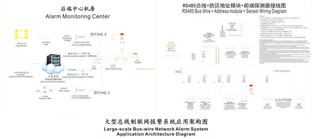
Best Practices for Reliable Alarm Bus Design
To ensure long-term performance:
- Follow EN 50131-1 and UL 681 guidelines
- Use shielded cabling in EMI-prone environments
- Avoid mixing power and data grounds incorrectly
- Document topology and labeling clearly
- Perform periodic impedance and voltage checks
Field data from integrators shows that proper bus design reduces service callouts by over 30% during the first two years of operation.
Conclusion: Designing a Reliable Alarm Bus Architecture
Choosing the right bus topology is not merely a wiring decision—it defines the reliability, maintainability, and security integrity of the entire alarm system.
- Daisy-chain topology offers simplicity and cost efficiency for smaller, linear installations.
- Star topology delivers resilience, clarity, and scalability for mission-critical environments.
By understanding the technical trade-offs and applying proven engineering practices, designers can build alarm systems that perform reliably throughout their lifecycle.
For system designers and engineers, mastering alarm bus topology is not optional—it is foundational.
References
- EN 50131-1:2020 – Alarm Systems – Intrusion and Hold-Up Systems – System Requirements, BSI.
- UL 681 – Installation and Classification of Burglar and Holdup Alarm Systems, UL Solutions.
- Bosch Security Systems – Modular Intrusion Panel Technical Documentation.
- NXP Semiconductors – RS-485 and Differential Bus Design Guidelines.
- Security Industry Association (SIA) – Best Practices for Alarm System Installation.