
In the high-stakes world of industrial security, a single undetected intrusion can cost millions in downtime, stolen assets, or compromised safety. For project managers overseeing sprawling factories, expansive industrial parks, or complex engineering sites, traditional standalone alarm systems simply collapse under the weight of 1,000+ devices. Latency spikes, false alarms flood control rooms, and centralized oversight becomes impossible. That’s where a properly designed network alarm system transforms vulnerability into unbreakable resilience.
This definitive, hands-on guide equips security decision-makers, technical engineers, procurement specialists, and operations leaders with the exact blueprint to build a scalable network alarm system capable of handling thousands of intrusion detection points in real time. Drawing from decades of field experience in anti-theft alarm deployments, we focus on practical architecture using MQTT for lightweight, event-driven messaging, TCP for mission-critical reliability, and cloud integration for infinite scalability. You’ll walk away with actionable steps, proven design patterns, and insider tactics that prevent common failures while delivering sub-second alarm response across massive sites.
Whether you’re retrofitting an existing factory perimeter or designing a greenfield industrial park, this guide solves your core pain points: unreliable device connectivity at scale, overwhelming data volumes, integration headaches with CCTV, and the constant threat of downtime in harsh environments. Follow it meticulously, and you’ll deploy a system that not only detects intrusions instantly but scales effortlessly as your project grows—driving down costs, boosting uptime, and giving you the confidence to expand without fear.

Why Traditional Alarm Systems Fail at Scale — And Why a Modern Network Alarm System Succeeds
Large-scale projects demand more than basic door contacts and sirens. A factory with 50 buildings, a park spanning 200 acres, or an engineering site with remote unattended zones can easily exceed 1,000 intrusion sensors, motion detectors, glass-break devices, and perimeter beams. Legacy wired or dial-up systems struggle with:
- Device overload: Single-point controllers max out at a few hundred connections. Beyond that threshold, the entire system degrades unpredictably.
- Communication bottlenecks: Polling-based protocols create latency and bandwidth waste. When hundreds of zones check in sequentially, real-time response becomes a myth.
- Lack of central visibility: Operators drown in siloed alerts without unified dashboards. There’s no way to correlate an alarm in Building A with a simultaneous perimeter breach on the east fence.
- Harsh environment challenges: Dust, vibration, temperature extremes, and power fluctuations in factories cause frequent dropouts and corrupted transmissions.
- Integration gaps: No seamless linkage to existing CCTV for verified video pop-ups on alarm. Guards receive text alerts but cannot visually confirm what triggered the sensor.
- Scalability dead ends: Adding 100 more sensors often requires ripping out and replacing core infrastructure, making growth prohibitively expensive.
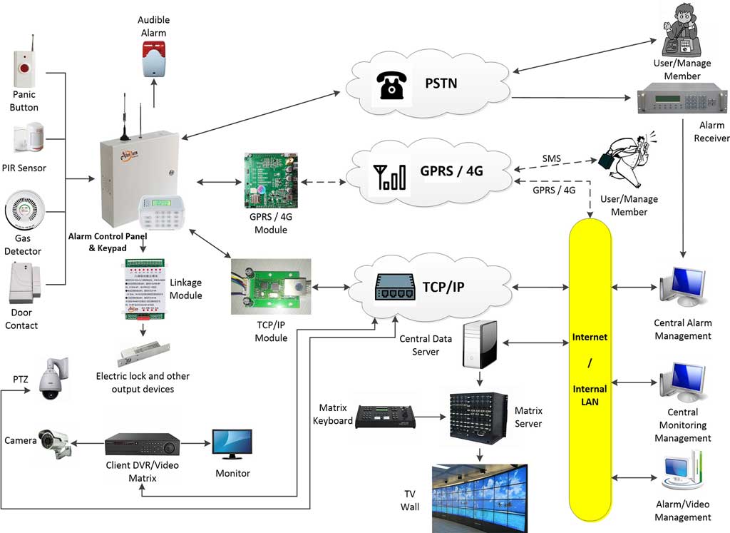
A true network alarm system flips this script entirely. It leverages IP-based communication for real-time, bidirectional data flow. Alarms publish instantly across the network, triggering automated responses like video verification, guard dispatch, or law enforcement alerts. When built with MQTT, TCP, and cloud layers, it achieves horizontal scalability — adding devices without re-architecting the core.
Real-world impact? Projects using scalable network alarms report 70–90% faster response times, 50% fewer false positives through intelligent filtering, and centralized management that cuts maintenance costs by 40%. For procurement teams buying in bulk, this means lower total cost of ownership (TCO) and future-proofing against expansion.
What a Modern Network Alarm System Actually Covers
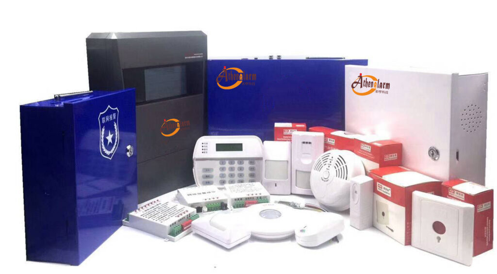
A mature network alarm system for large-scale projects is not just a collection of sensors tied to a server. It is an integrated, multi-layer security ecosystem that typically includes:
- Intrusion detection layer: PIR motion sensors, dual-tech detectors, door/window contacts, glass-break sensors, vibration detectors, active infrared perimeter beams, microwave barriers, and electric fence alarm interfaces.
- Communication layer: Wired Ethernet, Wi-Fi, 4G/LTE, RS-485 bus, and MQTT/TCP/IP protocols — often used in combination depending on the site layout.
- Control and processing layer: Network-capable alarm control panels with addressable zone modules, local processing logic, tamper protection, and UPS backup.
- Management layer: Central alarm monitoring software (server + client architecture) that aggregates alarms, manages users, generates reports, and links to CCTV for real-time video pop-up on alarm.
- Response layer: Automated siren activation, SMS/email/app push notifications, guard dispatch, video recording triggers, and escalation workflows to law enforcement.
This layered approach ensures that even if one layer encounters a problem — a network segment goes down, a sensor malfunctions, or a power outage strikes a remote zone — the other layers continue operating independently, maintaining overall system integrity.
Core Architecture: MQTT, TCP, and Cloud — The Foundation of Scalability
At the heart of any robust network alarm system for 1,000+ devices lies a hybrid protocol stack. Understanding each component — and how they interact — is essential before you purchase a single piece of hardware.
MQTT (Message Queuing Telemetry Transport)
MQTT is the lightweight publish-subscribe champion for large-scale intrusion alarm networks. Sensors and panels act as “publishers” that push alarm events to a central broker using hierarchical topic strings. Subscribers — your management software, mobile app, analytics engine — receive only the topics they need.
Why it matters for intrusion alarms at scale:
- The protocol overhead is minimal (2-byte fixed header), which is critical in bandwidth-constrained factory environments or remote parks relying on 4G.
- Quality of Service (QoS) levels give you direct control: QoS 0 for routine heartbeats (no delivery guarantee needed), QoS 1 for alarm events (at-least-once delivery), and QoS 2 for highest-priority critical zone breaches (exactly-once delivery).
- Retained messages allow the broker to store the last-known state of each sensor, so a new subscriber (e.g., a guard’s mobile client logging in mid-shift) immediately receives the current alarm status of every zone without waiting for the next event.
- The publish-subscribe model means adding 200 new sensors in a new factory wing does not require reconfiguring existing devices. You simply provision new clients and define their topics.
Practical MQTT topic design for 1,000+ devices:
A well-designed topic hierarchy is the single most important decision you will make in an MQTT-based alarm system. A poor namespace creates subscription nightmares and makes filtering impossible. Use this structure as your starting point:
/[site_id]/[building_or_zone]/[floor_or_area]/[sensor_type]/[device_id]/[event_type]
Example:
/factory_A/building_03/floor_2/pir/PIR-0274/intrusion
/factory_A/perimeter/north_fence/beam/BEAM-018/tamper
/park_B/gate_7/door_contact/DC-104/open
This hierarchy allows operators to subscribe to /factory_A/# for all factory events, or /factory_A/perimeter/# for only perimeter alerts. It makes zone-level filtering, shift-based subscriptions, and analytics aggregation straightforward from day one.
TCP/IP
TCP provides reliable, connection-oriented communication for scenarios where MQTT’s lightweight model is insufficient. In a large-scale alarm deployment, TCP is typically used for:
- Panel-to-server configuration pushes: Arming schedules, zone definitions, and user credential updates sent from the management server to panels require guaranteed, ordered delivery. TCP ensures commands arrive intact.
- Heartbeat supervision: Panels send periodic keep-alive packets over a persistent TCP socket. If the socket drops, the server immediately flags that panel as offline and triggers an alert — catching communication failures before they become security gaps.
- High-bandwidth video linkage: When an alarm triggers a live RTSP video stream from a linked CCTV camera, that stream travels over TCP to guarantee frame integrity.
- Fallback command channel: If an MQTT broker temporarily loses a client connection, a parallel TCP command channel can issue emergency arming/disarming instructions directly to a panel.
The practical configuration: panels maintain a persistent TCP connection to the alarm server on a defined port (commonly 6000–6010 in professional systems). The server monitors connection state in real time and logs any disconnection with a timestamp.
Cloud Integration Layer
The cloud layer transforms a site-level alarm system into an enterprise-wide security platform. For multi-site factories, park chains, or engineering firms with projects across regions, this is where real operational leverage lives.
Recommended architecture:
- On-premises MQTT broker cluster: Handles local alarm processing with sub-100ms latency. Even if internet connectivity fails, local alarms still trigger, records are stored, and responses are dispatched.
- Cloud synchronization: Alarm events, device health data, and video metadata are mirrored to a cloud platform (AWS IoT Core, Azure IoT Hub, or a private server). This enables global dashboards, cross-site analytics, and remote management from any internet-connected device.
- Edge computing at gateway level: Industrial IoT gateways perform first-pass filtering before publishing to the broker — reducing broker load and eliminating obvious false alarms (e.g., filtering out PIR triggers during known maintenance windows).
Cloud platform selection criteria for alarm systems:
- Supports MQTT over TLS natively.
- Provides a rules engine to route alarm events to different response channels (SMS gateway, email server, ticketing system, guard dispatch app).
- Offers time-series data storage for alarm history and device health trending.
- Scales horizontally without re-architecting — critical when your device count grows from 1,000 to 5,000.
- Has a documented SLA of 99.9% or higher uptime for the message broker service.

Step 1: Comprehensive Planning and Requirements Gathering (Weeks 1–4)
Never skip this phase. Ninety percent of scaling failures in large alarm deployments trace back to poor planning. Rushed procurement and “we’ll figure it out during installation” thinking consistently leads to rework, cost overruns, and security gaps that take months to close.
1.1 Conduct a Full Site Risk Assessment
Start with a structured walkthrough of every location where the system will operate. This is not a quick tour — it is a formal, documented assessment that forms the technical foundation of your entire design.
Step-by-step risk assessment process:
- Obtain site plans, architectural drawings, or CAD files for every building and outdoor area. If these don’t exist, commission a drone survey to generate accurate layout maps.
- Walk every perimeter, entry point, and internal zone with a security specialist. Mark every door, window, loading dock, skylight, roof access hatch, utility corridor, and fence line that represents a potential intrusion path.
- Identify high-value asset locations: server rooms, cash offices, equipment stores, raw material warehouses, production lines with expensive machinery, fuel storage, and chemical storage.
- Assess environmental conditions zone by zone: indoor climate-controlled areas, outdoor perimeters exposed to rain and temperature extremes, dusty production floors, vibration-heavy machine rooms, and areas with chemical fumes that could affect sensor performance.
- Map power infrastructure: identify locations of main distribution boards, available circuit capacity for alarm equipment, and sites where power outages are most likely (remote zones, outdoor cabinets).
- Document existing security systems: any existing CCTV cameras, access control systems, fire alarm systems, or legacy intrusion panels that the new network alarm system will need to coexist with or integrate into.
- Identify threat vectors specific to your site: perimeter breaches from adjacent properties, insider risk from night-shift personnel in sensitive areas, vehicle intrusion through gates, roof access from adjacent structures.
The output of this step is a risk matrix that ranks every zone by threat level and asset value. High-risk, high-value zones get layered detection (e.g., perimeter beam + PIR + door contact + glass-break). Lower-risk zones may be adequately covered by a single sensor type.
1.2 Define the Complete Device Inventory
Based on your risk assessment, build a detailed device inventory. For a 1,000+ device deployment, a realistic breakdown might look like this:
| Device Type | Quantity (Example) | Notes |
|---|---|---|
| PIR/Dual-tech motion sensors | 450 | Indoor zones, corridors |
| Active infrared perimeter beams | 160 | Fences, outdoor boundaries |
| Door/window contacts | 220 | All entry points |
| Glass-break detectors | 80 | Windows in high-value areas |
| Vibration detectors | 60 | Safes, vaults, server racks |
| Alarm control panels | 55 | Networked, addressable |
| Zone expansion modules | 110 | Addressable bus modules |
| IoT gateways/network routers | 30 | Industrial grade, dual-SIM |
| Integrated CCTV cameras | 80 | ONVIF compatible |
| Siren/strobe units | 75 | Indoor + outdoor |
Add a 20–30% growth buffer to every category. Projects invariably discover new zones during installation, and having pre-provisioned headroom prevents emergency procurement delays.
1.3 Define Performance KPIs
Before selecting any hardware or software, define your non-negotiable performance targets. These KPIs will govern every subsequent technical decision.
- End-to-end alarm latency: Maximum time from sensor trigger to operator alert. For most industrial projects, 2 seconds is the target; for critical zones (server rooms, vaults), push for sub-1-second.
- System availability: Target 99.99% uptime across the alarm communication infrastructure. This drives your redundancy decisions.
- False alarm rate: Target less than 1% of alarm events being false positives after intelligent filtering is applied. Higher false alarm rates desensitize operators and cause critical events to be ignored.
- Concurrent connections: Your MQTT broker cluster must handle the maximum number of simultaneous connected devices comfortably — plan for 1.5x your device count to accommodate bursts during failover.
- Recovery time objective (RTO): If a primary broker node fails, how quickly must the system failover to a secondary node? For mission-critical sites, this should be under 30 seconds.
1.4 Compliance and Standards
Large industrial and engineering projects often face regulatory requirements for their security systems. Align your design with relevant standards from the outset to avoid costly redesigns during commissioning:
- UL 1076 (Proprietary Burglar Alarm Units and Systems — North America)
- EN 50131 series (Alarm systems — Intrusion and hold-up systems — Europe)
- IEC 62676 (Video surveillance systems for use in security applications)
- IEC 60839 (Alarm and electronic security systems)
- Local fire and safety codes that may govern how alarm systems interact with evacuation procedures
For cloud and data elements, address GDPR (EU), PDPA (Singapore/Thailand), or CCPA (California) requirements for any personal data processed — including video recordings and user access logs.
1.5 Budget Modeling and ROI Calculation
Build a detailed 3-year total cost of ownership model before finalizing your design. Include:
- Hardware: panels, sensors, gateways, UPS units, cable/conduit materials
- Software: alarm management platform licenses, cloud hosting fees, MQTT broker licensing (if commercial)
- Installation: labor, commissioning, testing
- Ongoing: annual maintenance contracts, cloud subscription costs, battery replacements, training
- Risk mitigation value: projected theft prevention, insurance premium reductions, regulatory compliance cost avoidance
For a 1,000-device factory deployment, payback periods of 12–18 months are realistic when theft prevention and operational efficiency gains are factored in.
1.6 Create a Phased Rollout Matrix
Divide your deployment into priority phases. Never attempt to commission 1,000+ devices simultaneously — the configuration burden and troubleshooting complexity make this approach almost guaranteed to fail.
A typical phased approach:
- Phase 1 (Weeks 1–12): Critical production zones, server rooms, main entry/exit points — the 20% of locations that carry 80% of risk.
- Phase 2 (Weeks 13–20): Secondary buildings, loading areas, secondary perimeter sections.
- Phase 3 (Weeks 21–28): Remote zones, expansion areas, full perimeter completion.
This approach lets your team learn on the live system, fine-tune configurations, and resolve integration issues before extending to the full site.
Step 2: Hardware Selection and Procurement (Weeks 5–8)
Hardware selection for a large-scale network alarm system is not purely a cost exercise. Cheap hardware in an industrial environment quickly becomes expensive when panels fail in dusty production areas, sensors produce excessive false alarms in temperature-variable outdoor zones, or firmware cannot be updated remotely when vulnerabilities are discovered.
2.1 Alarm Control Panels
The alarm control panel is the brain of each local zone. For a network alarm system at scale, every panel must be IP-enabled with TCP/IP and 4G communication modules as standard — not as optional add-ons.
Critical selection criteria:
- Network communication: Native TCP/IP module (not an external adapter) for reliable, low-latency communication with the central server. Built-in 4G as automatic fallback when wired network is unavailable.
- Zone capacity: Panels should support at least 64–128 addressable zones natively, with bus expansion modules that allow scaling to 256+ zones per panel without replacing the base unit.
- MQTT client support: Increasingly, modern industrial alarm panels include an embedded MQTT client that publishes alarm events directly to a broker. This eliminates an intermediate gateway layer and reduces latency.
- Tamper protection: Physical tamper switches on the enclosure, power tamper detection, and zone tamper monitoring — all generating independent alarm events on any interference.
- Operating temperature: Minimum range of -20°C to +55°C for indoor industrial environments; -40°C to +70°C for panels installed in outdoor enclosures.
- Battery backup: Built-in charger and support for sealed lead-acid or lithium backup batteries providing at least 8 hours of standby operation.
- Addressable zone modules: Support for RS-485 bus addressable modules (single-zone and 8-zone types) that allow running a single 4-wire cable to a terminal block serving multiple sensors — dramatically reducing installation labor in large buildings.
Practical procurement tip: Request firmware changelogs from your shortlisted panel manufacturers. A manufacturer that has released regular firmware updates over the past 3 years is maintaining their product; one that hasn’t updated firmware in 3 years likely will not support your system through its 10-year operational life.
2.2 Intrusion Detection Sensors
Sensor selection must be matched to the specific detection challenge of each zone, not generalized across the entire site.
Indoor zones (production floors, corridors, offices):
- Dual-technology PIR + microwave detectors: Combining two independent detection principles dramatically reduces false alarms in industrial environments where forklifts, conveyor belts, and HVAC airflow can trigger standard single-technology PIR sensors. Both technologies must trigger simultaneously before an alarm is generated.
- PIR curtain sensors: Ideal for doorways, windows, and corridors where a narrow detection beam is needed rather than wide-area coverage. Curtain sensors reliably detect persons crossing a threshold without triggering on lateral movement.
- Wide-angle PIR sensors: For large open floor areas, choose models with 120° or 180° horizontal detection angles to minimize the number of sensors needed per zone.
- Door/window contacts: Use surface-mounted or flush-mounted magnetic contacts on every opening. For roller doors and industrial shutters, use heavy-duty contacts rated for the operating cycle of the door mechanism.
- Glass-break detectors: Acoustic glass-break sensors can cover up to 9 meters of radius in ideal conditions. In factory environments with high ambient noise, test carefully before finalizing placement — you may need shock-type vibration sensors mounted directly on glass frames instead.
Outdoor perimeter zones:
- Active infrared (AIR) beam detectors: The most reliable technology for defined perimeter lines — fence lines, building perimeters, gated entry points. Multi-beam models (4-beam) are more resistant to birds, wind-blown debris, and small animals than single-beam types.
- Microwave barriers: For perimeter detection in areas where line-of-sight beam alignment is difficult, microwave barriers can detect movement through foliage and in fog or rain conditions.
- Fence vibration sensors: For chain-link or steel panel fencing, cable vibration sensors or fence-mounted seismic sensors detect cutting, climbing, or impact on the fence structure. These publish tamper-type alarm events that can be handled separately from breach events.
- Passive infrared outdoor detectors: When used outdoors, ensure detectors are rated for the full operating temperature range and have anti-masking features. Models with temperature compensation maintain detection performance across seasonal temperature swings without recalibration.
Environmental ratings: For any sensor not in a climate-controlled indoor environment, require IP65 minimum ingress protection rating. For sensors in washing areas, outdoor locations exposed to rain, or chemical processing areas, specify IP66 or IP67.
2.3 Network Infrastructure — Gateways, Switches, and Routers
The network infrastructure is the connective tissue of your alarm system, and it receives far less attention than it deserves during procurement.
Industrial-grade managed switches:
- Specify managed switches with VLAN support so alarm traffic can be isolated on its own network segment (critical for security and performance).
- Power over Ethernet (PoE) capability simplifies deployment by powering IP cameras and smaller alarm devices through the same cable.
- Operating temperature range must match the environment. Standard commercial switches fail in factory temperatures above 50°C — specify industrial variants accordingly.
- Look for redundant ring topology support (e.g., ERPS/G.8032) for critical sections of the network, allowing the switch fabric to recover from a single link failure in under 50ms.
4G/LTE industrial routers:
- Dual-SIM support is non-negotiable for backup communications. When the primary SIM’s carrier has a regional outage, the router automatically switches to the secondary SIM on a different carrier.
- VPN client capability (IPsec or OpenVPN) built into the router firmware ensures all 4G communications to the central server are encrypted end-to-end.
- DIN rail mounting for installation in standard electrical cabinets alongside alarm panels.
- Watchdog functionality that automatically reboots the router if it stops responding to the management platform — eliminating the most common cause of “silent failures” in remote 4G-connected sites.
2.4 Video Integration Components
For a large-scale network alarm system, CCTV is not optional — it is an integral part of the intrusion verification workflow.
Key requirements:
- ONVIF Profile S compliance: This open standard ensures cameras from different manufacturers (Hikvision, Dahua, Axis, and others) can be integrated with the alarm management software without proprietary adapters.
- PTZ preset positions: Cameras covering large outdoor areas should support programmable preset positions that the alarm software can command automatically when a specific zone alarm triggers.
- IR illumination: For perimeter cameras operating at night without artificial lighting, built-in IR illuminators with at least 30-meter effective range are needed.
- Analytics-capable cameras: Cameras with built-in motion detection, line-crossing detection, or intrusion zone detection can serve as a secondary verification layer, reducing false alarm response.
Video integration workflow: When zone PIR-0274 triggers an intrusion alarm, the alarm software automatically commands Camera CAM-12 (pre-mapped to that zone) to move to Preset 3 (covering the triggered area), begins recording, and displays the live RTSP stream in a pop-up window at the operator console. The operator sees the alarm and the video simultaneously — within 2 seconds of the sensor triggering.
Step 3: Designing the Communication and Network Architecture (Weeks 9–12)
This is where the scalability of your system is engineered into existence. Decisions made here determine whether your system handles 1,000 devices smoothly or buckles under load six months after go-live.
3.1 Deploy the MQTT Broker Cluster
For a 1,000+ device deployment, a single MQTT broker is an unacceptable single point of failure. Start with a clustered setup from day one.
Step-by-step broker cluster setup:
- Select your broker software: EMQX and HiveMQ are the most widely deployed options for industrial IoT applications at scale. Both support clustering, TLS, X.509 authentication, and horizontal scaling. EMQX has a free community edition that handles up to 10,000 concurrent connections per node — sufficient for most industrial alarm deployments.
- Provision three broker nodes minimum: Three nodes provide a quorum for cluster consensus algorithms. Two-node clusters cannot handle a node failure without manual intervention.
- Assign roles: In EMQX, all nodes in a cluster are peers. Configure each node with the same cluster name and list all peer node addresses in the configuration file. The cluster self-organizes after startup.
- Configure a load balancer in front of the cluster: Use HAProxy or NGINX with TCP passthrough (not HTTP load balancing — MQTT runs over TCP). Distribute incoming connections across broker nodes using least-connections balancing. This is the single IP/hostname that all your alarm devices connect to.
- Configure persistent sessions: Set
clean_session = falseon all alarm device clients. This instructs the broker to queue messages for offline clients and deliver them when the connection is re-established — ensuring no alarm events are lost during brief network interruptions. - Set maximum inflight messages: Configure
max_inflight = 32or higher per client on the broker side to handle burst events when multiple sensors trigger simultaneously. - Configure retained messages: Enable retained messages so that each sensor publishes its current state (armed, triggered, tampered, offline) as a retained message. New subscribers receive the complete current state picture immediately.
Broker tuning for 1,000+ alarm devices:
- Set
max_connectionsper broker node to at least 5,000 (well above your device count, to accommodate reconnection bursts after a network event). - Enable connection rate limiting to prevent reconnection storms from overwhelming the broker after a site-wide power event.
- Configure alarm-specific topic ACLs: an intrusion sensor should be able to publish only to its own topic, never to another device’s topic or to control topics.
3.2 Layer TCP for Panel Communication
Configure your alarm control panels for persistent TCP connections to the alarm server in parallel with MQTT.
Panel TCP configuration steps:
- On each panel, configure the alarm server’s IP address and port (e.g., 192.168.10.100, port 6001).
- Set the heartbeat interval to 30 seconds. The panel sends a keep-alive packet every 30 seconds; if the server doesn’t receive one within 90 seconds (3 missed heartbeats), it marks the panel as offline and raises a supervisory alarm.
- Enable automatic reconnection with exponential backoff (30s, 60s, 120s delays) to prevent reconnection storms.
- On the server side, configure the TCP listener to maintain a connection state table for every panel, with offline detection latency matching your KPI (typically 90–120 seconds).
3.3 Network Segmentation — VLAN Architecture
Alarm traffic must be isolated from general enterprise IT traffic. This is not just a security best practice — it is a reliability requirement. A bandwidth-intensive activity on the corporate network (a firmware update, a backup job) should never be able to degrade alarm communication performance.
Recommended VLAN structure:
| VLAN ID | Purpose | Traffic Type |
|---|---|---|
| VLAN 10 | Alarm devices | Sensor/panel to MQTT broker |
| VLAN 20 | CCTV cameras | RTSP video streams |
| VLAN 30 | Alarm management servers | Server-to-broker, server-to-database |
| VLAN 40 | Operator workstations | Management software clients |
| VLAN 50 | 4G/cellular backup | Out-of-band management |
Configure inter-VLAN routing rules using a firewall that allows alarm device traffic (VLAN 10) to reach only the MQTT broker (VLAN 30) — never corporate systems. Apply strict QoS policies that prioritize VLAN 10 and VLAN 30 traffic over all other traffic classes.
3.4 Redundancy and Failover Design
Communication path redundancy:
Every panel requires at least two independent communication paths. The primary path is wired Ethernet through the managed switch infrastructure. The secondary path is 4G via a dual-SIM industrial router. The panel (or its gateway) automatically switches to 4G when Ethernet connectivity is lost and reverts to Ethernet when it recovers — transparently, without manual intervention.
Broker node failover:
When a load-balanced MQTT device loses its connection to a broker node, the broker load balancer (HAProxy/NGINX) routes the reconnection attempt to a healthy node. The persistent session stored by the broker cluster is picked up by the new node, and queued messages are delivered. Total failover time from client perspective: 15–45 seconds depending on reconnect backoff configuration.
Power redundancy:
- All panels must operate on UPS-backed circuits. Size UPS units for a minimum of 8 hours of standby at full panel load.
- Outdoor equipment enclosures in remote zones without reliable power should be provisioned with solar panels + deep-cycle battery systems as primary power.
- Server infrastructure must be on a UPS with automatic generator transfer capability for sites where extended outages are possible.
Step 4: Cloud Platform and Central Management Software Integration (Weeks 13–16)
The alarm management software is the operational hub of your entire network alarm system. Every alarm event, device health status, operator action, and report flows through it. Choosing and configuring this software correctly determines whether your security team can operate the system effectively or drowns in complexity.
4.1 Alarm Management Software Architecture
Professional network alarm management software follows a server-client architecture:
- Server component: Installed on a Windows Server or Linux host (physical or virtual). The server maintains the connection to the MQTT broker, processes incoming alarm events, applies rules, stores all data in a database, and serves client connections.
- Client component: Installed on any Windows workstation connected to the server (over LAN, WAN, or VPN). Operators use the client to monitor live alarm status, respond to events, configure zones, run reports, and manage users. Multiple simultaneous clients can connect to a single server.
- Mobile app: Many modern platforms provide iOS/Android apps for supervisors and on-call security managers, delivering push notifications and limited remote management capability.
For redundancy, deploy two server instances in an active-passive configuration, with a shared database back-end. If the active server fails, operators reconnect their clients to the standby server within minutes.
4.2 Core Features to Configure and Validate
Real-time alarm handling:
Configure each alarm point in the software with the following parameters:
- Zone name and physical location description.
- Assigned camera (for automatic video pop-up on alarm trigger).
- Response instructions displayed to operators (e.g., “Zone PIR-0274: North Warehouse, Bay 3. Dispatch Guard Team 2 immediately. Do not enter alone.”).
- Escalation rules: if alarm is not acknowledged within 3 minutes, escalate via SMS to the duty manager.
- Schedule-aware arming: automatically arm this zone from 18:00 to 06:00 on weekdays, 24 hours on weekends.
Video integration configuration:
- In the software’s camera management section, add each ONVIF camera by IP address, port, username, and password.
- Map each camera to the alarm zones it covers using a zone-to-camera mapping table.
- Configure the PTZ preset position to display when each zone triggers.
- Test the video pop-up by manually triggering a test alarm from the affected zone and confirming the correct camera view appears within 2 seconds.
User roles and access control:
- System administrator: Full configuration access. Only 2–3 trusted individuals.
- Security supervisor: Can acknowledge alarms, run reports, configure responses but cannot change system configuration.
- Operator: Can view alarms, acknowledge events, and dispatch guards. No configuration access.
- Viewer: Read-only access to live status and historical reports. For site managers who need visibility but not operational control.
Reporting configuration:
Schedule automated daily reports to be emailed to site management:
- Alarm event log with timestamps, zone, response time, and operator who acknowledged.
- Device health summary: any panels offline, sensors with low battery, communication faults.
- False alarm analysis: zones with unusually high trigger rates that may need sensitivity adjustment.
- Weekly trend analysis: alarm frequency by zone, time of day, and day of week — invaluable for staffing and patrol route optimization.
4.3 Cloud Synchronization and Remote Access
Configure your on-premises server to synchronize alarm event data and device health records to the cloud platform at regular intervals (or in real time for critical events). This provides:
- Off-site backup of alarm records (important for insurance claims and legal proceedings).
- Access for regional security managers who need oversight across multiple sites without VPN complexity.
- Platform for AI-based analytics — for example, identifying patterns like recurring breaches in a specific zone every Tuesday night, indicating a specific vulnerability or employee behavior worth investigating.
For remote access security, mandate VPN + multi-factor authentication for any cloud or remote management access. Never expose alarm management interfaces directly to the public internet.
Step 5: Step-by-Step Deployment and Installation (Weeks 17–24)
Execute deployment in controlled phases. Attempting to commission all zones simultaneously creates a troubleshooting nightmare where a single misconfiguration affects the entire system and becomes nearly impossible to isolate.
Phase 1: Site Preparation
- Install cable trays, conduits, and junction boxes along all planned cable routes before any devices are mounted. Working around unprepared cable runs after devices are in place costs significantly more time than doing it correctly at the start.
- Mount alarm panel enclosures in secure, ventilated locations — away from high-EMI equipment (motors, frequency drives, welding equipment) and in areas accessible for maintenance but secured against unauthorized access.
- Pull all cable runs and label both ends clearly using a consistent labeling convention (panel ID + zone number + cable function). Poor cable labeling is consistently one of the top causes of extended troubleshooting time during and after installation.
- Install network switches, routers, and patch panels in locked, ventilated cabinets. Confirm operating temperatures inside cabinets with a thermometer under worst-case conditions before closing them up permanently.
Phase 2: Hardware Rollout
- Mount sensors: Position each sensor according to the risk map, ensuring overlapping coverage with no blind spots. For PIR sensors, mount at the recommended height (typically 2.0–2.4 meters) with the detection zone oriented to maximize cross-target movement detection — the geometry that produces the most reliable triggering.
- Wire sensors to zone modules: Connect wired sensors using twisted-pair cable (minimum 0.5mm²). Use end-of-line (EOL) resistors at the sensor end of each zone circuit to enable supervision — the panel monitors the resistance of each zone at all times and alerts on both open-circuit (cut wire) and short-circuit (wired tampering) conditions.
- Connect panels to network: Terminate Ethernet cables at the panel’s network module using a quality cable tester to verify all eight conductors before powering up. Insert 4G SIM cards and confirm cellular registration before relying on 4G for any functionality.
- Power up in sequence: Power up panels one by one, confirm each establishes connectivity to the broker/server, and verify its zone inputs before moving to the next. Never power up all panels simultaneously — troubleshooting is dramatically harder when everything comes online at once.
Phase 3: Software Configuration and Device Provisioning
- Provision each device in the management software: Assign a unique device ID, configure its network address (static IP recommended for panels), and map it to its physical location in the software’s site map.
- Define all zones: For each panel, configure zone type (instant, delayed, 24-hour, perimeter, etc.), zone name, assigned response procedure, and linked camera.
- Configure the MQTT rules engine: Define event-processing rules such as:
- “If zone type = perimeter AND time = 22:00–06:00, generate HIGH PRIORITY alarm and send SMS to duty manager immediately.”
- “If zone = maintenance area AND time = 08:00–17:00 weekdays, generate LOW PRIORITY alarm (log only, no siren).”
- “If five or more zones trigger within 60 seconds, generate MASS ALARM event and page all security personnel.”
- Set up CCTV integration: Map every camera to its coverage zones, configure PTZ presets, and verify video pop-up for each zone.
- Configure arming schedules: Program automatic arm/disarm schedules for each zone or zone group. Confirm schedules are correct for all time zones if your project spans multiple geographic regions.
Phase 4: Staged Go-Live
- Arm Phase 1 zones (critical production areas) first and operate in monitored mode for 72 hours. During this period, every alarm — including false alarms — is logged, analyzed, and used to fine-tune sensor sensitivity and positioning.
- Brief all site personnel about the new system before go-live: what triggers an alarm, how to disarm during authorized access, and who to contact if they accidentally trigger an alert.
- Establish a clear false alarm logging procedure: every false alarm is documented with the triggering sensor, time, probable cause, and corrective action taken. This creates an audit trail and drives systematic improvement.
Critical wiring and configuration reference:
Panel Ethernet port → Labeled patch cable → Patch panel port → Industrial managed switch → Uplink to core network → MQTT broker server.
Panel configuration: set broker IP/hostname, port (1883 for unencrypted testing, 8883 for TLS production), client ID (unique per panel), username and password, and keepalive interval of 30 seconds.
JSON alarm payload format:
{
  "device_id": "PANEL-B03-F2",
  "zone_id": "PIR-0274",
  "zone_name": "North Warehouse Bay 3",
  "event_type": "intrusion",
  "severity": "high",
  "timestamp": "2025-10-14T22:47:03Z",
  "armed_state": "armed_away",
  "battery_level": 87
}
This standardized payload structure allows the alarm server to parse any device’s events with the same code, simplifying both initial development and long-term maintenance.

Step 6: Rigorous Testing, Validation, and Optimization (Weeks 25–28)
No network alarm system for 1,000+ devices should be declared operational until it has been deliberately stressed, broken, and proven to recover — under controlled conditions.
6.1 Functional Testing
Walk-test every sensor in the system individually. This means physically triggering the detection zone of each PIR, breaking each beam, opening each door contact, and confirming:
- The correct zone name and location appear at the operator console.
- The correct camera view pops up automatically.
- The correct response instructions display.
- The siren/strobe activates (if configured for that zone).
- The alarm is logged with the correct timestamp and severity.
- The event appears in the mobile app notification (if configured).
Record the test result for every zone in a commissioning test sheet. Any zone that fails must be diagnosed and retested before the project is signed off. This documentation also serves as the baseline for future maintenance audits.
6.2 Scalability Stress Testing
Before declaring the system live, simulate the maximum expected load — and then exceed it by 50%.
How to conduct a broker load test:
- Use an MQTT load testing tool such as EMQTT-Bench or JMeter with the MQTT plugin.
- Simulate 1,500+ virtual alarm clients all connecting simultaneously and publishing at normal operating rates.
- Monitor broker CPU, memory, and message throughput. Confirm that latency remains below your 2-second KPI across all virtual clients even at peak load.
- Simulate a burst scenario: 200 clients trigger alarms simultaneously (the scenario where a perimeter breach triggers multiple overlapping zones). Confirm the broker handles the burst without message loss.
6.3 Failover and Redundancy Testing
- Broker node failure: Disconnect one broker node from the network while the system is under load. Confirm all connected clients reconnect to surviving nodes within 45 seconds and no alarm events are lost.
- Wired network failure: Physically disconnect the Ethernet uplink from a panel enclosure. Confirm the panel switches to 4G within 30 seconds and continues publishing alarms. Reconnect Ethernet and confirm automatic reversion.
- Server failure: Shut down the active alarm management server unexpectedly. Confirm operators can reconnect to the standby server within 5 minutes and historical data is intact.
- Power failure: Cut power to a panel enclosure. Confirm UPS maintains operation. Restore power and confirm the panel reboots and reconnects without manual intervention.
6.4 False Alarm Tuning
After functional testing, operate the system in monitoring mode for at least one week before full go-live. During this period, analyze every alarm event:
- PIR sensors triggering from HVAC airflow: raise the detection threshold or reposition the sensor.
- Beam detectors triggering from vegetation movement: trim vegetation or switch to multi-beam models.
- Door contacts showing intermittent false alarms: check magnet alignment and contact gap; replace if necessary.
- Sensors in factory areas triggering from machinery vibration: add vibration dampening mounts or switch to dual-tech detectors.
The goal is to reach your <1% false alarm rate KPI before the system is relied upon for live security operations.
6.5 Security Penetration Testing
Engage a qualified penetration tester to attempt to compromise the alarm system from the network:
- MQTT broker: attempt to publish unauthorized alarm events or subscribe to alarm topics without valid credentials.
- TLS: attempt to intercept communications between panels and the broker.
- Management software: attempt to access the operator interface without valid credentials.
- 4G communication: attempt to intercept panel-to-server communication on the cellular link.
Any vulnerabilities found during penetration testing must be remediated before the system is declared operational. Document the penetration test report and remediation actions for compliance records.
Step 7: Security Hardening — Non-Negotiable for Intrusion Alarm Systems
A network alarm system is a security system, but it is also an IP-networked system — which means it is itself a potential attack target. Compromising your alarm system is one of the most effective ways for a sophisticated intruder to neutralize your defenses before a break-in. Every item below is mandatory, not optional.
Authentication
- Every alarm device (panel, sensor gateway, camera) must authenticate to the MQTT broker with a unique client ID, username, and password. Never use shared credentials across devices — if one device is compromised, shared credentials expose every device.
- For highest-security installations (data centers, financial institutions, government facilities), replace username/password authentication with X.509 mutual TLS certificate authentication. Each device receives a unique client certificate signed by your internal Certificate Authority.
- Implement strict Access Control Lists (ACLs) in the broker: each device may publish only to its own assigned topics and subscribe only to topics it legitimately needs. A perimeter sensor should never be able to publish to the control topic that arms/disarms zones.
Encryption
- Enable TLS 1.3 on all MQTT communications. Never deploy production systems with plain (unencrypted) MQTT on port 1883.
- Rotate TLS certificates annually, or immediately if a device is decommissioned or suspected of compromise.
- Encrypt the alarm database and ensure backups are encrypted before they leave the site.
Monitoring the Alarm System Itself
- Deploy an intrusion detection system (IDS) that monitors the alarm network’s MQTT traffic for anomalies: unexpected connection attempts, devices publishing to unauthorized topics, abnormal message rates that could indicate an active attack.
- Configure alerts for any broker authentication failure. Three consecutive authentication failures from a single client ID should trigger an automatic lockout and an alert to the security team.
- Monitor management software login attempts. Lock accounts after five failed attempts and require administrative reset.
Firmware and Software Hygiene
- Maintain a registry of every device’s current firmware version.
- Configure OTA (over-the-air) firmware update capability for all network-connected devices. When a manufacturer releases a security update, deploy it across all 1,000+ devices without requiring physical access.
- Only accept signed firmware images that have been verified against the manufacturer’s public key — preventing supply chain attacks where malicious firmware is substituted during an update.
- Remove or disable all default credentials, unused network services (Telnet, HTTP management interfaces), and debugging ports on every device before deployment.
Step 8: Alarm System Integration with Physical Security Operations
A technically excellent network alarm system delivers no real-world security value if the people responsible for responding to it are poorly trained or lack clear procedures. The alarm system and the human security operation must be designed together.
Standard Operating Procedures for Alarm Response
Define a written procedure for every category of alarm your system can generate. At minimum, create procedures for:
- High-priority intrusion alarm (armed zone, out-of-hours): Operator acknowledges within 30 seconds, reviews video pop-up to visually confirm, dispatches guard team if confirmed, calls law enforcement if intrusion is verified, escalates to duty manager.
- Low-priority alarm (scheduled maintenance area, business hours): Operator logs the event, contacts the zone supervisor to confirm authorized activity, closes event with notes.
- Tamper alarm: Immediate escalation regardless of time. A tamper event means someone is physically interfering with security equipment — treat it as a confirmed security incident.
- Supervisory alarm (panel offline, communication fault): Maintenance technician dispatched within 4 hours to inspect the affected panel.
- Mass alarm event (5+ zones simultaneously): Pre-defined major incident response protocol activated — all guard teams deployed, law enforcement notified, site management alerted.
Post these procedures at every operator workstation. Conduct quarterly drills to ensure all operators can execute them correctly under pressure.
Guard Patrol Integration
Use the alarm system’s zone arming schedules and alarm history to optimize guard patrol routes. Zones with historically higher alarm frequencies during specific time windows should receive increased patrol attention during those periods. When a zone triggers an alarm and a guard is dispatched, the alarm management software should track guard acknowledgment and arrival at the zone — creating an auditable response record.
Maintenance Procedures
A 1,000+ device system requires a structured preventive maintenance program to sustain performance:
- Monthly: Remote health check of all panels via management software. Review device connectivity logs for intermittent communication issues.
- Quarterly: Physical inspection of sensor mounting and alignment for outdoor devices. Check battery voltage on all UPS units. Test 4G failover on a sample of panels.
- Annually: Full walk-test of all zones. Replace batteries in wireless devices. Renew TLS certificates. Review and update alarm response procedures. Conduct penetration test.
- Continuous: Monitor automated daily health reports. Any device showing communication faults or abnormal alarm rates triggers a same-week investigation.
Step 9: Ongoing Maintenance, Monitoring, and Future Scaling
Day-to-Day Operations
The alarm management software’s automated health dashboard should be the first thing your security operations team checks at the start of every shift. Key metrics to review daily:
- Devices offline or with communication faults (target: zero).
- Zones with abnormally high alarm rates from the previous 24 hours (investigate for false alarm sources).
- Failed authentication attempts at the MQTT broker (investigate as potential security incidents).
- UPS battery health across all sites.
Configure the system to send daily health summary emails to the security operations manager and IT infrastructure team automatically. Don’t rely on operators to remember to check these metrics manually.
Scaling Beyond 1,000 Devices
One of the primary advantages of an MQTT/TCP/cloud architecture is that scaling is an operational process, not a re-engineering project. When you add a new factory wing, a new building, or a new site to the network alarm system:
- Provision the new alarm zone IDs and topic paths in the broker’s ACL configuration.
- Add panel(s) and sensor devices following the same commissioning process used in initial deployment.
- Add the new zones, devices, and cameras to the alarm management software.
- Brief operators on the new areas.
- Conduct a walk-test of all new zones before activating.
The existing broker cluster, management server, and cloud platform absorb the new devices without any downtime to the running system. If broker capacity approaches 80% utilization, add a new node to the cluster — a process that takes less than an hour with properly documented runbooks.
Analytics Evolution
As your network alarm system accumulates months of event data, that data becomes operationally valuable beyond its immediate security function:
- Breach pattern analysis: Which zones, at what times of day, on what days of the week, see the highest alarm frequencies? This drives targeted patrol scheduling and physical security upgrades.
- False alarm root cause tracking: Which specific sensor models produce the most false alarms in industrial environments? This informs future procurement decisions.
- Response time benchmarking: How quickly are alarms being acknowledged and responded to? Are there operators or shifts with consistently slower response times that need additional training?
- Predictive maintenance: Sensors with increasing communication fault rates or intermittent connectivity are often heading toward failure. Proactive replacement based on trend data is far less disruptive and costly than emergency replacement after a failure.
Feed this data into a business intelligence tool or even a simple Excel-based reporting template and review it monthly with site security management.
Common Pitfalls and How Experienced Engineers Avoid Them
These are the mistakes that consistently appear in post-project reviews of large-scale network alarm deployments — and that are entirely avoidable with proper planning.
Pitfall 1: Underestimating MQTT broker load
The mistake: sizing the broker for current device count, ignoring reconnection bursts, heartbeat traffic, and retained message overhead. The fix: start clustered from day one, size each node for 3x your expected device count, and load-test before go-live. The cost difference between a single-node and a three-node broker cluster is trivial compared to the cost of a system failure during a security incident.
Pitfall 2: Poor topic namespace design
The mistake: using flat, unstructured topic names (e.g., “alarm1”, “sensor_23”) that make zone-level filtering and analytics impossible. The fix: design the full topic hierarchy on paper before a single device is configured. Get it reviewed by the team that will manage the system long-term. Changing a topic namespace after 1,000 devices are provisioned is an enormous, error-prone project.
Pitfall 3: Ignoring harsh environment requirements
The mistake: specifying commercial-grade hardware for industrial environments, then experiencing rampant failures within the first year. The fix: specify industrial-grade hardware with appropriate ingress protection ratings, operating temperature ranges, and vibration/shock ratings for every zone’s specific environment. Request datasheets and match specifications to actual conditions — not assumed ones.
Pitfall 4: Deploying TLS as an afterthought
The mistake: commissioning the system on plain MQTT (port 1883) for convenience during testing, then “adding TLS later.” TLS almost never gets added later. The fix: deploy with TLS enabled from the first day of commissioning. Yes, it adds complexity during initial setup. It also prevents your intrusion detection system from being compromised by someone with basic network access and a packet capture tool.
Pitfall 5: No documented cable labeling convention
The mistake: cables are run, panels are installed, and labeling is done inconsistently or not at all. When a fault occurs two years later, nobody can identify which cable serves which zone without an hours-long physical trace. The fix: define and enforce a labeling convention before installation begins. Every cable end gets a label: Panel ID + Zone Number + Cable Function. Take photographs during installation. Store this documentation in the alarm management platform and in a physical binder at each panel location.
Pitfall 6: Skipping operator training
The mistake: delivering a technically excellent system to operators who don’t understand how to use it effectively, leading to slow response times, incorrect alarm handling, and frustrated security teams who lose confidence in the system. The fix: build a structured training program that includes hands-on practice with the management software, drills using simulated alarm scenarios, and written procedures for every alarm category. Certify each operator before they take independent shifts. Provide refresher training when the system is updated or expanded.
Real-World Applications: What a Correctly Deployed Network Alarm System Achieves
The following scenarios represent realistic outcomes when the approach described in this guide is applied rigorously.
Large manufacturing facility (1,200 devices, three production buildings + perimeter): Before deployment, perimeter intrusions at night went undetected until discovered during the morning shift. Response to confirmed alarms took an average of 14 minutes due to siloed alert systems and poor CCTV integration. After deploying a network alarm system with MQTT broker cluster, integrated CCTV video pop-up, and structured response procedures, confirmed intrusion response time dropped to under 90 seconds. Theft incidents in the first year after deployment fell by 78% compared to the prior year.
Industrial park covering 50+ hectares (1,600+ devices across 18 tenant facilities): The park management company needed centralized visibility across all tenant alarm systems without accessing tenant-confidential CCTV. By deploying a multi-site MQTT architecture with separate tenant topic namespaces and a shared park management dashboard, the security operations center gained real-time visibility of all perimeter alarm status. The 4G fallback on remote perimeter zones eliminated the dead zones that had plagued the previous wired-only system.
Engineering construction site (temporary deployment, 400 devices across a 12-month project): Construction sites present unique challenges: the security perimeter changes monthly as the project progresses, and all infrastructure must be temporary and relocatable. Using wireless sensors with cellular IoT gateways, MQTT over 4G to a cloud broker, and a hosted management software instance, the project security team deployed, relocated, and decommissioned sensor zones on a weekly basis — tracking materials worth millions with a system that could follow the site’s changing geometry.
Conclusion: Your Next Move
Building a scalable network alarm system for 1,000+ devices is a serious engineering and operational discipline. When done correctly — with rigorous planning, properly specified hardware, a well-designed MQTT/TCP/cloud communication architecture, tight security hardening, and trained operators working from clear procedures — it delivers a level of intrusion protection that is simply not achievable with traditional standalone alarm systems.
The steps in this guide are not theoretical. They represent the accumulated experience of engineers who have commissioned large-scale alarm systems across factories, industrial parks, bank networks, campus facilities, and engineering sites in demanding real-world conditions. Follow this blueprint from planning through to post-deployment maintenance, and you will build a system that detects threats faster, generates fewer false alarms, scales without disruption, and remains operationally sound for the full life of the project.
If you are ready to move from planning to procurement, or need customized control panels, scalable alarm management software, or integration support for your specific factory, park, or engineering project, our team of anti-theft alarm specialists can review your site plans, advise on hardware specification, and support your deployment from initial design through to commissioning and beyond.
Contact us via WhatsApp or our website for a no-obligation technical consultation. Your project’s scale is not a problem — it is exactly what this system is built for.