

I. Introduction
In many intrusion detection deployments, even highly experienced installers encounter recurring issues such as false alarms, unstable sensor communication, or unexpected panel failures. In most cases, the root cause is not the hardware itself—but improper intrusion alarm panel wiring. A single reversed polarity wire, an undersized cable, or a poorly grounded loop can compromise the entire security system.
Proper wiring is fundamental to ensuring stability, reducing maintenance costs, and meeting compliance requirements for professional-grade burglar alarm installations. This guide highlights the essential wiring requirements for intrusion alarm panels and their connected devices, offering technical clarity for installers, system engineers, product managers, and procurement professionals responsible for selecting or deploying commercial and residential intrusion detection systems.
Throughout this guide, you will learn industry-proven practices for alarm panel connections, burglar alarm system cabling, power distribution, zone supervision, device integration, and code compliance—helping you avoid errors that commonly occur during installation and bulk deployments.
II. Understanding Intrusion Alarm Panels and Their Components
What Is an Intrusion Alarm Panel?
An intrusion alarm panel is the central processor of a burglar alarm system. It receives signals from sensors, monitors zone status, manages power, communicates with monitoring centers, and controls outputs such as sirens or relays. All these functions rely heavily on stable, correct wiring.
Common Connected Devices
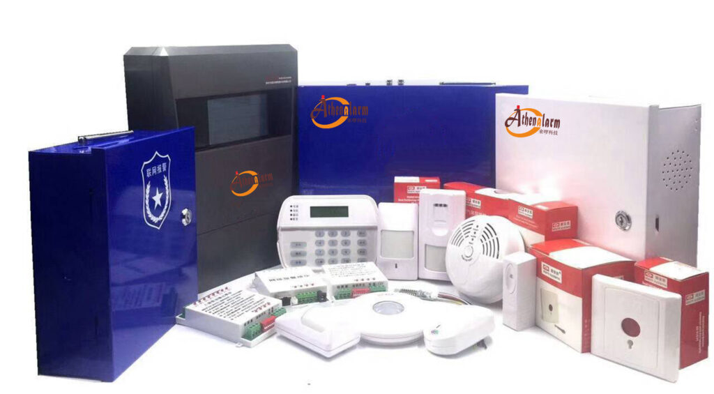
Typical components wired to an intrusion alarm panel include:
- Door/window magnetic contacts
- PIR motion detectors and dual-tech sensors
- Glassbreak detectors
- Shock/vibration sensors
- Keypads and touch panels
- Indoor/outdoor sirens
- Communication modules (PSTN, IP, GSM/LTE)
- Auxiliary relays, automation outputs, and expansion boards
Each device category has distinct electrical characteristics and cabling requirements that must be respected to ensure long-term reliability.
Wired vs. Wireless Considerations
Although wireless intrusion devices continue to grow in popularity, wired systems remain the preferred choice for:
- Critical infrastructure
- Data centers
- Warehouses
- Government and industrial sites
Wired alarm panel connections provide lower latency, predictable power delivery, and improved tamper protection.
III. General Wiring Principles and Best Practices
Cable Types and Specifications
For most intrusion detection wiring requirements:
- 22 AWG to 18 AWG stranded cable is recommended for sensors and low-power peripherals.
- Shielded twisted pair (STP) is preferred for data buses, communication lines, or high-interference environments.
- 4-core or 6-core cables are commonly used for motion detectors and keypads.
- 18/2 or 18/4 cables are standard for sirens, relays, and auxiliary power connections.
Choosing the correct gauge prevents voltage drop, ensures signal integrity, and maintains compliance with UL and EN wiring guidelines.
Grounding and Shielding
Electromagnetic interference (EMI) is a frequent cause of false alarms. Use these best practices:
- Ground shields at one end only (typically the panel end) to avoid ground loops.
- Do not run alarm cabling parallel to high-voltage lines.
- Maintain separation from fluorescent lighting, motors, or HVAC units.
For sensitive zones—such as glassbreak sensors—shielded cable is strongly recommended.
Distance Limitations
While limits vary by manufacturer and device design, general guidelines include:
- Keypads/data buses (RS-485 or proprietary): 1,000–4,000 ft depending on topology
- Zone loops: 500–1,000 ft for supervised wiring
- Siren outputs: keep under 300 ft unless using proper gauge cable
For larger buildings, consider repeaters, power extenders, or zone expanders.
Safety and Code Compliance
Compliance with low-voltage wiring codes is mandatory. Relevant regulations include:
- NEC Article 760 – Fire and intrusion alarm system wiring
- UL 681 – Installation of burglar and holdup alarm systems
- EN 50131 – Intrusion and hold-up system requirements for Europe
Using the correct cable category (e.g., CL2, CL3, FPLR) ensures legal and safe installation.
IV. Specific Wiring Requirements for Key Intrusion Alarm Components
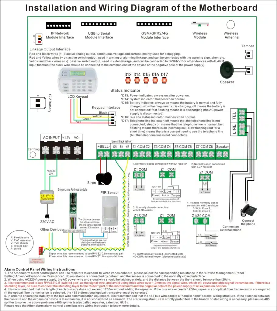
1. Power Supply & Backup Battery Wiring
Key requirements include:
- Connect AC transformers using approved low-voltage cabling and observe polarity.
- Maintain proper fuse ratings to protect the panel’s power circuit.
- Wire backup batteries using the panel’s dedicated leads to ensure seamless switchover during outages.
- Add tamper circuits for metal enclosures to maintain system integrity.
Voltage drop should always be calculated when powering multiple devices externally.
2. Zone Wiring for Sensors
Intrusion alarm panels typically support:
- Normally Closed (NC) circuits
- Normally Open (NO) circuits
- Supervised loops with End-of-Line (EOL) resistors
Best practices:
- Place EOL resistors at the device, not inside the panel enclosure, to ensure proper supervision.
- Use series wiring for multiple NC devices but avoid parallel connections unless the device is supervised.
- Use 4-wire connections for powered sensors such as PIR detectors.
3. Keypad and User Interface Wiring
Keypad wiring varies by panel brand but generally involves:
- 4-wire or 6-wire data bus (e.g., RS-485, A/B+, GND, power)
- Assign unique addresses to each keypad
- Maintain consistent bus topology—avoid star wiring unless supported
- Terminate the bus when required by the manufacturer
Stable data bus wiring is essential for preventing keypad communication errors.
4. Wiring Output Devices and Expansion Modules
For sirens, strobes, and relays:
- Observe maximum current limits on AUX and BELL outputs
- Use 18 AWG for outdoor sirens
- Add flyback diodes for relay coils if not already included
- Fuse external power supplies appropriately
Relay outputs can interface with access control, automation, or CCTV systems.
5. Communication Module Wiring
Modern intrusion alarm panels may include:
- PSTN dialer terminals (TIP/RING)
- Ethernet/IP connectors
- GSM/LTE modules with SIM slots
- Serial communication ports (TTL, RS-232, RS-485)
Key wiring considerations:
- Maintain proper isolation between low-voltage bus lines and communication wiring
- Protect outdoor cables with surge suppressors
- Follow manufacturer-specific RJ-terminal wiring schemas
V. Common Wiring Challenges and Troubleshooting Tips
Frequent Wiring Issues
- Open circuits caused by loose terminal screws
- Short circuits due to pinched or damaged cable insulation
- Ground loops creating erratic sensor signals
- Incorrect EOL resistor placement leading to zone faults
Troubleshooting Steps
- Verify continuity using a multimeter
- Check zone resistance values against the panel specifications
- Inspect field wiring for splices, moisture, or corrosion
- For complex sites, perform segment-by-segment isolation to identify faulty branches
Real-World Example
In a large warehouse installation, repeated false alarms occurred during forklift operation. Investigation revealed inadequate shielding on long PIR detector runs. Replacing the cable with shielded 22/4 stranded wire and grounding at the panel eliminated all false triggers. This example highlights the importance of proper cabling in environments with strong EMI sources.
VI. Compliance, Standards, and Procurement Considerations
Relevant Industry Standards
- UL 681 – Wiring methods and classifications for burglary systems
- NFPA 70 / NEC Article 760 – Low-voltage and signaling circuit requirements
- EN 50131-1 – System requirements for intrusion installations
- ASIS and ESA guidelines – Best practices for alarm system engineering
Implications for Procurement and Product Managers
When sourcing intrusion alarm panels in bulk:
- Prioritize models with modular wiring architectures
- Ensure compatibility with both 2-wire and 4-wire sensor types
- Evaluate supported cable distances and bus configurations
- Assess built-in surge protection and power management circuitry
- Confirm availability of wiring manuals, diagrams, and certification compliance
Future-Proofing
Emerging technologies such as Power over Ethernet (PoE) for hybrid IP-based alarm panels are becoming increasingly relevant. Procurement teams should ensure long-term scalability and backward compatibility with traditional wiring infrastructures.
VII. Conclusion
Correct wiring is one of the most critical factors influencing the performance, reliability, and longevity of an intrusion alarm panel. By following the detailed wiring requirements and best practices covered in this guide—covering zone supervision, data bus connections, grounding, power distribution, and communication modules—you can significantly reduce false alarms, maintain compliance with UL/EN standards, and ensure optimal system stability.
For project-specific designs, always refer to manufacturer installation manuals and conduct a thorough on-site assessment. Proper planning and adherence to industry standards will support safer installations and more informed procurement decisions.