
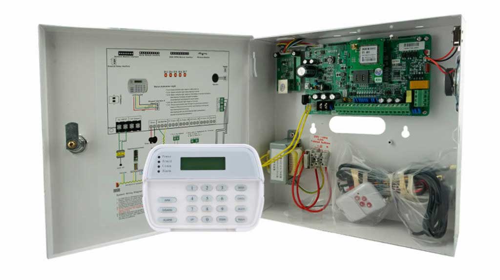
Alarm zone configuration and wiring form the foundation of reliable burglar alarm systems, empowering installers to build setups that reduce false alerts, enhance fault detection, and ensure swift responses. For professionals in system design, grasping zone types, mapping strategies, and advanced wiring techniques in burglar alarms tackles key pain points such as ambiguous reporting, tampering vulnerabilities, and regulatory compliance. This guide delivers actionable expertise, blending industry standards with real-world solutions to optimize intrusion detection and long-term performance.
Defining Alarm Zones in Burglar Systems
An alarm zone serves as a logical segment in a burglar alarm setup, grouping sensors or devices to monitor targeted areas or functions. This division enables the control panel to handle inputs as unified entities, delivering accurate breach identification. Inadequate alarm zone configuration can lead to response delays, needless emergency calls, and diminished user trust.
For installers, zones extend beyond mere connection points—they are pivotal for security strategy. A precisely mapped and wired zone, for example, can specify an intrusion at “Front Lobby Door” instead of a generic “Perimeter Alert,” speeding up verification and resolution.
Key Zone Types in Intrusion Detection
Choosing appropriate zone types customizes system responses to unique site risks. Below is an overview of standard types, including roles, devices, and tips for peak burglar alarm efficiency.
Entry/Exit Zones
These zones offer a buffer time for arming or disarming, avoiding unintended alarms from routine access.
- Common Applications: Main entrances, garages, or paths near keypads.
- Configuration Tips: Adjust entry delays to 30-45 seconds according to user routines; excessive delays may allow intrusions to go unnoticed. Keep dissimilar entries separate for precision.
- Installer Solution: To curb repeated false alarms, review site flow and tweak delays in the alarm panel‘s “Zone Settings” menu: Select the zone, enter revised values, and validate through entry simulations.
Perimeter Zones
These target building exteriors, delivering immediate alerts when the system is armed for prompt threat detection.
- Typical Devices: Door/window magnetic contacts or fence vibration sensors.
- Best Practices: Organize by facade (e.g., “North Perimeter Windows”) for rapid checks. Configure as “Instant” in armed modes.
- Problem-Solving: In windy locations prone to glass-break false triggers, add dual-verification: Set the panel to demand two activations in 10 seconds before alerting.
Interior Follower Zones
Activated post-entry zones, these oversee internal areas while permitting movement during grace periods.
- Devices Used: PIR motion sensors or microwave units in occupied spaces.
- Key Rule: Tie them to entry delays to avoid alarms from approved users.
- Practical Fix: For homes with pets, activate “Pet Immunity” on suitable detectors: In setup, access the zone editor, enable the feature, and fine-tune sensitivity to overlook animals below 40 pounds.
24-Hour Zones
Constantly operational, these address urgent, non-deactivatable risks irrespective of arming status.
- Examples: Panic buttons, flood sensors, or panel tamper detectors.
- Installation Note: Limit bypassing to administrators for unbroken safeguarding.
- Troubleshooting: If tamper faults arise, check wiring: Unplug the loop, test resistance (aim for 1-5k ohms), and swap components if inconsistent.
Specialized Zones: Silent and Supervisory
Silent zones notify monitoring stations quietly, ideal for hold-up scenarios.
- Setup Steps: Link to concealed buttons and program as “Silent Panic”: Go to “Zone Type,” choose “Silent,” connect to central reporting, and confirm via test.
Supervisory zones track system vitality, flagging issues like battery depletion or signal loss to preempt breakdowns.
Fundamentals of Zone Wiring
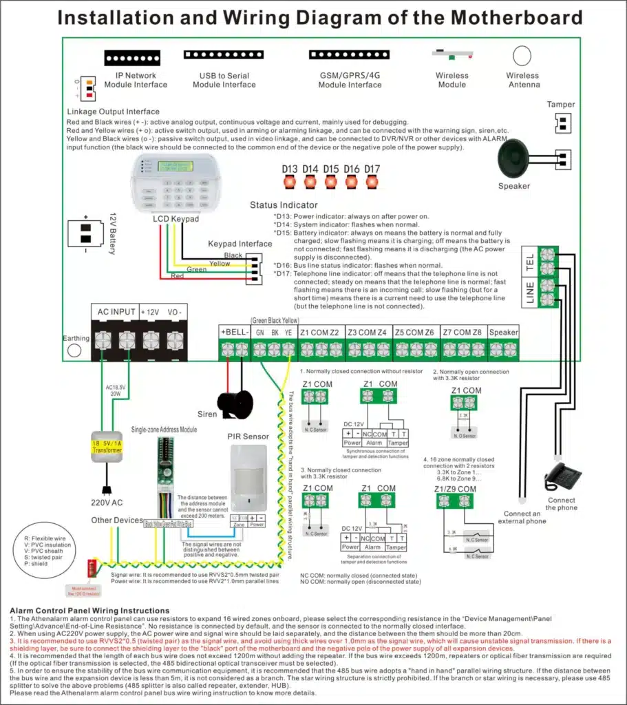
Zone wiring links sensors such as door contacts or motion detectors to the control panel via loops. Basic approaches rely on unsupervised normally closed (NC) or normally open (NO) contacts. NC loops stay closed when intact, triggering on openings like breaches or cuts. NO loops remain open securely and close on events. NC is preferred for superior tamper resistance, as wire severance mimics a violation, unlike NO where it might disable the sensor.
Unsupervised loops lack fault monitoring, allowing undetected shorts or cuts. Advanced methods add supervision via resistors, enabling ongoing circuit health checks to thwart bypassing and cut false alarm rates from wiring issues.
Advanced Wiring Techniques for Robust Supervision
Elevate zone integrity with these proven strategies, focusing on fault detection and resilience.
Implementing Supervision with Resistors
End-of-line resistors (EOL) are essential for monitoring. Single EOL detects shorts, displaying set resistances (e.g., 5600Ω secure in DSC panels). Double EOL (DEOL) offers detailed state separation: secure at 5600Ω, violated at 11,200Ω, short at 0Ω, open at infinite. Install resistors at the sensor for anti-tamper benefits—consult panel manuals for compatibility, like DSC models, and verify post-setup with a multimeter.
Types of Supervised Wiring Configurations
- No EOL (Unsupervised): Basic and insecure; NC secure/short at 0Ω, violated/open at infinite. Skip for pro installs due to tampering risks.
- Single EOL: Resistor at end; secure matches value, short at 0Ω, open/violated at infinite. Good for entry-level but mixes opens with breaches.
- Double EOL (DEOL): Dual resistors; full state discernment for top tamper spotting. Restrict to one NC sensor per zone; position at sensor to block shorts.
While fire zones favor NO supervision, prioritize burglar-focused NC here.
Class A vs. Class B Wiring Styles
Adapted from fire protocols for added redundancy in burglar alarms:
- Class B: Single path; breaks cut off downstream devices. Economical but vulnerable—similar to standard supervised loops.
- Class A: Loop-back redundancy; sustains operation on partial failures. Costlier with more cabling, suited for vital perimeters in addressable systems.
Select per risk level: Class B for homes, Class A for businesses.
Wiring Multiple Detectors to a Single Zone
Maximize limited panel zones (e.g., 8 on entry-level DSC) by grouping:
- NC Zones: Series connection; chain detectors, EOL at end. Example: Sequence three door contacts, then resistor.
- NO Zones: Parallel setup; shared terminals, EOL at farthest.
Cap at 5-10 devices for fault clarity. For active sensors (e.g., PIRs at 20-32mA), keep total under 550mA aux power.
Step-by-Step for Series NC Wiring:
- Locate terminals (e.g., Z and COM on DSC).
- Wire first sensor’s NC in loop.
- Chain others.
- Add EOL at last.
- Measure resistance: Secure equals EOL.
- Set zone type (e.g., instant perimeter).
Handling Tamper Loops and Anti-Bypass Measures
- Integrate tamper switches (e.g., in PIR covers) as 24-hour zones or series with main loops.
- Employ DEOL for cut/short alerts.
- Conceal wiring in conduits, ground to avoid EMI.
- Fortify panels with locks, code updates, and guarding sensors.
Cable Selection and Installation Best Practices
Opt for 22 AWG 4-conductor for standard runs, scaling to 18 AWG for >200m to curb voltage drops. Shielded types combat noise. Favor star/home-run layouts for diagnostics, adding surge guards.
- Types: 22/4 for basics; 18/2 for power-hungry; shielded twisted-pair for EMI; Cat5e for IP.
- Gauges for Distance: 0.5mm to 200m; 1.0-1.5mm farther (hold 9-19V at sensors).
- Topologies: Star for ease; loop for savings.
- Tips: Space power/signal 12″ apart; surge protect; label; add 15% length.
- Compliance: Follow UL 681, NEC (NFPA 70), regional rules.
Effective Zone Mapping Techniques
Mapping assigns devices to zones thoughtfully, merging coverage with detail. Flawed mapping yields unclear alerts, like floor-wide zones hindering localization.
Area-Based Mapping
Group by layout for user-friendly reports.
- Example: Zone 1: “Main Office – Windows and Doors”; Zone 2: “Warehouse – Motion Areas.”
- Advantages: Boosts monitoring speed; simplifies fixes via location knowledge.
- Implementation: Survey with sketches, mark sensors, then map in software via drag-and-drop.
Risk-Prioritized Mapping
Isolate high-stakes spots for priority handling.
- Case Study: Retail “Cash Room” as dedicated 24-hour zone with CCTV, cutting losses 25% per National Retail Federation data.
- Strategy: Interview clients for risks, assign urgent dispatch to key zones.
Steer clear of overloads—restrict to 5-10 devices.

Step-by-Step Configuration and Wiring Workflow
This practical sequence aids beginners in seamless alarm zone setup, weaving in wiring.
- Site Assessment: Inspect premises, log entries, traffic, weaknesses with visuals.
- Zone Planning: Catalog types (e.g., 2 entry, 4 perimeter), rank by risk in spreadsheets.
- Device Assignment and Wiring: Connect sensors to inputs using advanced methods (e.g., series NC with EOL); group in software: “Add Zone,” pick type, allocate by number.
- Attribute Setting: Define delays (30s entry), responses (audible/silent), codes; save and restart panel.
- Labeling and Documentation: Input clear names (e.g., “Rear Door Perimeter”); print lists.
- Testing Protocol: Arm, activate zones singly, check displays/apps; simulate faults, log, refine.
Adhering cuts errors 40%, per industry audits.
Avoiding Pitfalls in Zone Setup and Wiring
Common hurdles and remedies:
| Error | Consequences | Fix |
|---|---|---|
| Mixing Zone Types | Increased False Alarms | Segregate by function; reassign devices. |
| Vague Labeling | Delayed Response Times | Employ location-specific names; update in interface. |
| Ignoring Environmental Factors | Persistent Nuisances | Tune sensors for conditions, e.g., PIR for vents. |
| Non-Compliance with Codes | Legal Liabilities | Verify against standards in planning. |
| Overloading Zones/Wires | Ambiguous Faults | Limit devices; split for clarity. |
| Improper Resistor Placement | Weak Tamper Detection | Install at sensors; test resistances. |
Early fixes bolster durability.
Testing and Troubleshooting
Deploy multimeters for checks on continuity, resistance, voltage. Mimic issues like cuts (expect alarms in supervised). Record with diagrams and charts.
| Configuration | Secure Resistance | Violated | Short | Open | Advantages | Limitations |
|---|---|---|---|---|---|---|
| No EOL (NC) | 0Ω | Infinite Ω | 0Ω (no diff) | Infinite Ω (no diff) | Simple | No supervision |
| Single EOL | 5600Ω | Infinite Ω | 0Ω | Infinite Ω | Basic fault detect | Confuses open/violation |
| DEOL | 5600Ω | 11,200Ω | 0Ω | Infinite Ω | Full state diff | One sensor/zone |
| Class B | Varies by EOL | Alarm | Fault | Loss post-break | Cost-effective | No redundancy |
| Class A | Varies by EOL | Alarm | Fault | Partial function | Resilient | Higher cost |
Adhering to Industry Standards
Align configurations and wiring with benchmarks:
- UL 681 for burglar/holdup systems, stressing supervision and faults.
- EN 50131-1 for European intrusions, mandating clear IDs for risk grading.
- SIA CP-01 for false alarm cuts, requiring delays—compliance drops alarms 50-70%.
- NFPA 70 (NEC) for low-voltage wiring safety.
Review certifications to surpass mandates.
The Impact of Optimized Zones and Wiring
Well-executed zones and wiring deliver benefits: reduced fines ($200-500 U.S. average), faster responses, heightened trust. Per Electronic Security Association cases, they accelerate resolutions 30%. Ultimately, they evolve basic systems into resilient defenses, minimizing costs and maximizing protection as standards advance into 2025.
Future-Proofing and Integrations
Lay extra conduits, use modular enclosures for growth. Merge with CCTV using composites. Ground properly, add TVS diodes for surges. Schedule bi-annual checks.