
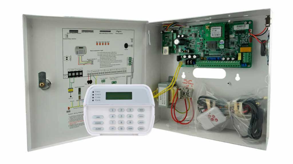
Modern intrusion alarm systems are rarely static. As buildings expand, usage patterns change, and security requirements increase, engineers are often asked to add zones, outputs, and peripherals without replacing the core control panel. The alarm bus expander is the key component that makes this possible—but it also introduces real engineering challenges.
This article explains, from a practical engineering perspective, how alarm bus expanders affect system load and signal routing, why these factors are frequently underestimated, and how to design expandable alarm architectures that remain stable, compliant, and reliable over time.
Alarm Bus Expanders: Function and Engineering Context
An alarm bus expander (also referred to as a zone expander or I/O expander) is a module connected to the control panel via a shared communication bus—commonly RS-485 or a proprietary supervised bus. Its purpose is to increase system capacity by adding:
- Additional intrusion zones
- Programmable outputs (relays, sirens, strobes)
- Keypads or interface modules
- Specialized inputs such as tamper or environmental sensors
In most intrusion alarm panels, native capacity is limited (typically 8–16 zones). Bus expanders allow systems to scale to 32, 64, or even 128 zones without replacing the panel. However, every expander becomes both a power consumer and a bus participant, directly influencing system load and routing behavior.
Understanding System Load in Expanded Alarm Systems
What “System Load” Really Means
In intrusion alarm engineering, system load has two dimensions:
- Electrical load – total current drawn from the panel or auxiliary power supplies
- Communication load – traffic, latency, and timing on the alarm bus
Both are affected by the number and placement of alarm I/O expanders.
Ignoring either can result in intermittent faults, false alarms, device drop-offs, or complete bus failure.
Electrical Load Impact of Alarm I/O Expanders
Each alarm bus expander draws current continuously, even when the system is idle. Typical values seen in field deployments include:
- Bus expander idle current: 30–60 mA
- Bus expander active current: 80–120 mA
- PIR detector: 15–25 mA
- Glass break detector: 20–30 mA
- Relay output (energized): 25–40 mA
Practical Load Calculation Method
Engineers should always calculate worst-case current, not average consumption.
Step-by-step approach:
- List all expanders and connected devices
- Use manufacturer maximum current values (not typical values)
- Add standby and alarm-state consumption together
- Compare the total to the panel’s rated auxiliary output
Design rule used in professional practice:
Do not exceed 70–80% of rated power output. This margin accounts for voltage drop, temperature variation, and battery aging.
Field audits consistently show that overloaded panels are a leading cause of unstable alarm behavior, especially during alarm events when multiple outputs activate simultaneously.
Voltage Drop: The Hidden Load Problem
Even when total current seems acceptable, voltage drop across long bus runs can cause expanders to malfunction.
Key contributors include:
- Long cable distances
- Undersized conductors
- Multiple expanders powered from the same branch
As a guideline, voltage at the farthest alarm bus expander should remain within ±5% of nominal (typically 12 VDC) under full load. Anything lower increases the risk of communication loss and false zone reporting.

How Bus Expanders Affect Alarm Bus Routing
Routing Is Not Just Cabling
Routing describes both:
- Physical topology (how devices are wired)
- Logical addressing and communication flow
As expanders are added, routing complexity increases exponentially if not planned correctly.
Common Alarm Bus Topologies and Their Risks
- Daisy Chain
- Simple to install
- Vulnerable to single-point failures
- Long chains increase signal attenuation
- Star Topology
- Reduces distance per branch
- Can overload the panel’s bus driver if not specified
- Often discouraged unless manufacturer-approved
- Segmented Bus (Best Practice)
- Multiple short branches
- Balanced electrical and communication load
- Easier fault isolation
Industry best practices consistently favor segmented, supervised bus layouts for systems with multiple alarm bus expanders.
Communication Load and Timing Issues
Each alarm I/O expander increases polling time on the bus. While modern panels handle this efficiently, excessive expanders can cause:
- Delayed zone updates
- Missed supervision polls
- Intermittent “module missing” faults
In real installations, engineers often observe these symptoms only under alarm conditions—when traffic spikes due to multiple zone changes and output activations.
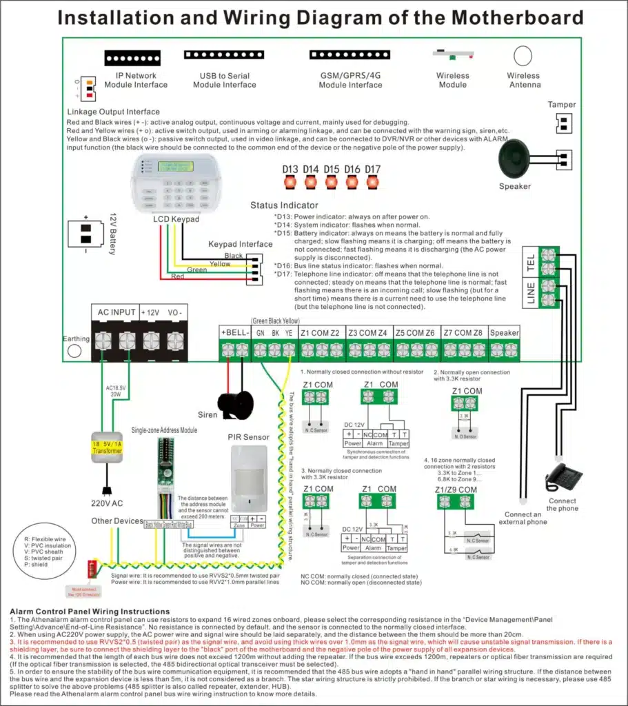
Design Best Practices for Load-Safe and Stable Expansion
Power Management Strategies
- Use auxiliary power supplies for remote expanders
- Power high-current outputs locally instead of from the panel
- Separate sensor power from communication power where supported
Many EN 50131 Grade 3 and Grade 4 designs explicitly require distributed power to maintain system integrity.
Routing and Cabling Recommendations
- Use twisted-pair cabling for data lines
- Maintain consistent grounding practices (shield grounded at one end only)
- Avoid mixing alarm bus wiring with high-voltage or RF-noisy cables
- Respect manufacturer limits for maximum bus length and device count
These measures significantly reduce EMI-related communication errors.
Addressing and Commissioning Discipline
Every alarm bus expander must have a unique address, correctly enrolled and documented. During commissioning:
- Enroll one expander at a time
- Verify stable communication before adding the next
- Perform full alarm-state load testing, not just standby testing
This process dramatically reduces future troubleshooting time.
Troubleshooting Load and Routing Problems in Existing Systems
When systems show unstable behavior after expansion, engineers should:
- Measure voltage at the farthest expander during alarm
- Temporarily disconnect expanders to identify load concentration points
- Inspect bus signal quality using diagnostic tools where available
- Check firmware compatibility between panel and expanders
In many real-world cases, issues attributed to “faulty expanders” are actually caused by cumulative load or routing design errors.
Conclusion: Expansion Requires Engineering, Not Just Hardware
Alarm bus expanders are essential for scalable intrusion alarm systems, but they are not plug-and-play accessories. Their impact on system load and routing directly determines whether an expanded system remains reliable or becomes unstable over time.
By calculating load correctly, designing disciplined routing topologies, and aligning expansion with recognized industry standards, engineers can deliver alarm systems that grow without sacrificing performance or compliance.
In professional intrusion alarm design, expansion success is decided on paper long before the first expander is installed.
References and Authoritative Sources
- National Fire Protection Association (NFPA). NFPA 72: National Fire Alarm and Signaling Code
- European Committee for Electrotechnical Standardization. EN 50131-1: Intrusion and Hold-Up Alarm Systems
- Electronic Security Association (ESA). Security System Design Best Practices
- Honeywell Security. Vista Series Installation and Setup Manuals
- Underwriters Laboratories (UL). UL 985 and UL 1023 Alarm System Standards
These documents provide the technical foundation for load calculation, routing design, and compliance in professional intrusion alarm systems.