

Introduction
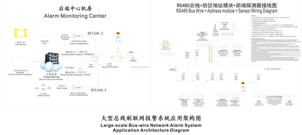
In modern intrusion alarm systems, relay modules play a critical role in bridging low-voltage control logic and high-current field devices such as sirens, strobes, magnetic locks, and external sounders. For professional security system integrators, understanding how to properly design, select, and deploy alarm relay modules is essential to system stability, safety, and long-term reliability.
This guide focuses specifically on high-current output management in alarm systems, addressing real-world challenges faced during installation and maintenance. It is written for integrators who need practical, field-ready knowledge, not theoretical electronics.
What Is an Alarm Relay Module?
An alarm relay module is an interface device that allows a low-power alarm control panel (typically 12–24V DC logic-level outputs) to safely control high-current or high-voltage loads. These loads often exceed the current capacity of alarm panel outputs and include:
- High-power sirens and sounders
- Strobe lights and beacons
- Magnetic door locks
- Electric strikes
- External warning devices
In intrusion alarm systems, relay modules serve three essential purposes:
- Electrical isolation between control logic and power loads
- Current amplification for devices exceeding panel output ratings
- System protection against overload, back-EMF, and electrical noise
Without proper relay integration, control panels are at high risk of output failure, false alarms, or permanent damage.
Why High-Current Output Management Matters
Effective high-current output management in alarm systems directly affects system stability and service life.
Poor current handling often leads to:
- Burned output transistors on alarm panels
- Intermittent siren activation
- False alarms caused by voltage drops
- Relay contact welding due to arcing
- System resets during alarm activation
According to industry field data shared by integrators at ISC West and SIA technical sessions, over 30% of alarm service calls are linked to output load mismanagement, not sensor failure.
High-current loads behave differently than logic circuits. Inductive devices—such as sirens, relays, and locks—generate voltage spikes when switched off. If unmanaged, these spikes degrade contacts and shorten equipment lifespan.
Types of Relay Modules Used in Alarm Systems
Understanding relay types is essential for selecting the right component.
1. Electromechanical Relay Modules
Common in intrusion systems due to simplicity and cost efficiency.
Advantages
- High current tolerance (typically 5–15A)
- Clear physical isolation
- Easy troubleshooting
Limitations
- Mechanical wear over time
- Slower switching
- Audible clicking
2. Solid-State Relay (SSR) Modules
Used in high-duty or noise-sensitive environments.
Advantages
- No mechanical wear
- Silent operation
- Long service life
Limitations
- Heat dissipation requirements
- Leakage current (important for low-load circuits)
3. Opto-Isolated Relay Modules
Common in professional alarm installations.
Benefits
- Excellent noise immunity
- Protects control panel logic
- Ideal for mixed-voltage environments

Common High-Current Challenges and How to Solve Them
1. Inductive Load Damage
Problem: Sirens and magnetic locks generate voltage spikes when de-energized.
Solution:
- Install flyback diodes (DC systems)
- Use MOVs or RC snubbers (AC systems)
2. Overheating Relay Contacts
Problem: Continuous high current causes thermal degradation.
Solution:
- Select relays rated at least 30–50% above actual load
- Use relays with heat-dissipating housings
3. Electrical Noise and False Triggers
Problem: EMI affects wireless sensors and panel inputs.
Solution:
- Use opto-isolated relay inputs
- Separate power and signal cabling
- Ground the enclosure properly
4. Voltage Drop Across Long Cable Runs
Problem: Devices fail to activate fully.
Solution:
- Increase conductor size
- Use local power supplies with relay isolation
Step-by-Step: Installing an Alarm Relay Module
This procedure applies to most intrusion alarm panels.
Step 1: Preparation
- Confirm load current requirements
- Verify relay ratings (voltage, current, duty cycle)
- Prepare 18 AWG (control) and 14–16 AWG (load) wiring
Step 2: Power Down
- Disconnect AC and backup battery
- Confirm zero voltage with a multimeter
Step 3: Connect Control Side
- Wire relay coil to panel output (PGM/AUX)
- Observe polarity for DC coils
- Secure terminals firmly
Step 4: Wire the Load Circuit
- Route the live conductor through COM → NO (or NC if required)
- Neutral and ground should bypass the relay
Step 5: Test Before Final Mounting
- Power system temporarily
- Trigger alarm event
- Measure current draw and voltage stability
Step 6: Secure and Label
- Mount inside a metal enclosure
- Label all wiring clearly
- Document in system drawings
This process ensures reliability and simplifies future servicing.
Best Practices for Long-Term Reliability
- Use UL 864–compliant components where applicable
- Avoid operating relays above 70–80% of rated load
- Inspect relay contacts every 6–12 months
- Replace mechanical relays after ~100,000 cycles in high-use systems
- Use smart relays with diagnostic feedback in enterprise systems
Field data from large commercial deployments shows that preventive relay replacement reduces unplanned alarm failures by over 40%.
Case Study: Commercial Alarm Upgrade
A logistics warehouse experienced intermittent alarm failures during nighttime arming. Investigation revealed 8A strobes controlled by relays rated at only 6A continuous load.
Solution implemented:
- Upgraded to 15A alarm relay modules
- Added surge suppression
- Rebalanced load distribution
Result:
Zero failures over 6 months and full compliance with NFPA 72 audible signaling requirements.
Key Takeaways
- Alarm relay modules are essential for safe high-current output control
- Proper sizing and protection prevent system failures
- High-current management directly impacts reliability and safety
- Professional installation standards significantly reduce service calls
By applying these principles, integrators can deliver stable, compliant, and future-ready alarm systems that perform reliably under real-world conditions.
Authoritative References
- Security Industry Association (SIA). Installation Best Practices Report
- UL 864 – Standard for Control Units and Accessories for Fire Alarm Systems
- NFPA 72 – National Fire Alarm and Signaling Code
- Bosch Security Systems – Relay Interface Technical Guide
- ISC West Conference Proceedings – Alarm Integration and Reliability Studies