
Key Points
- Research and industry practice show that the majority of panic button failures in real deployments stem from sabotage (wire cuts or shorts), human error (accidental bypass), or power loss—rather than the button press itself.
- Effective designs prioritize line supervision using end-of-line resistors (EOLRs) over simple NC/NO configurations, enabling detection of cuts, shorts, and tampering.
- Fail-safe wiring ensures alarms trigger on line faults, while power resilience relies on local battery-backed sirens and dual-path communication (IP + cellular) for reliable remote signaling.
- Scenario-specific adaptations (e.g., banks vs. warehouses) balance speed, discretion, and tamper resistance—evidence from commercial installations leans toward supervised NC loops with backup power as the most reliable approach.
Core Strategies Fail-safe panic button wiring flips traditional thinking: design for failure first. Instead of assuming perfect conditions, build systems that alarm when things go wrong—wire cuts, shorts, accidental shorts from tampering, or total power blackout. This approach dramatically reduces “silent failures” in high-stakes environments.
Power Resilience Use locally powered audible alarms and battery backups so panic functions remain active even if the main panel loses power. Dual-path communication ensures alerts reach monitoring centers reliably.
Practical Implementation Detailed steps and diagrams below show exactly how to wire for maximum protection.
Here are real-world examples of supervised panic button wiring setups in professional installations:
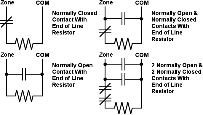
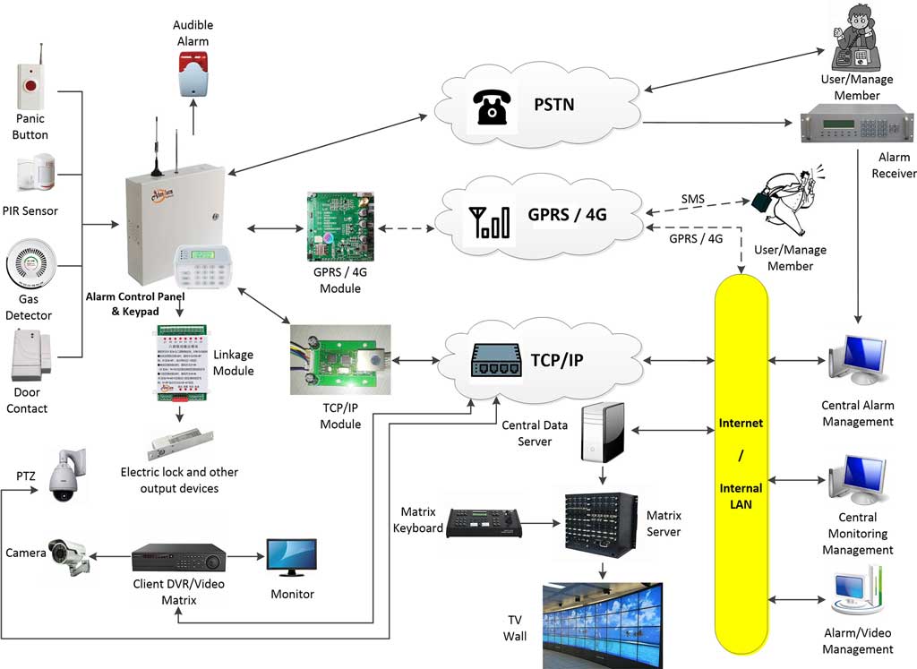
These visuals illustrate typical EOL resistor placements and multi-sensor loops commonly used in commercial panic systems.
Here’s a discreet under-desk panic button installation typical in banks and reception areas—discreet yet accessible:

Panic Alarm Systems Tucson | Emergency Alert Buttons for Business
Fail-Safe vs Fail-Secure in Panic Button Applications In door hardware, fail-safe unlocks on power loss for life safety, while fail-secure stays locked for security. For panic buttons in alarm systems, the logic shifts toward fail-safe signaling: any fault (cut, short, power loss) should trigger an alarm, not silence it. This ensures the system errs on the side of alerting rather than remaining quiet during compromise.
Line Supervision: The Real Key to Reliability NC/NO contacts alone are insufficient. Without supervision, cutting a NO wire disables the zone silently, and shorting an NC loop mimics normal state. End-of-line resistors solve this by allowing the control panel to constantly measure loop resistance and distinguish:
- Normal secure state
- Alarm (button pressed)
- Tamper (cut wire)
- Fault (short circuit)
Survey Note
Panic buttons remain one of the most critical yet misunderstood components in modern intrusion alarm systems. While brochures and basic tutorials focus on the simple act of pressing the button to trigger help, experienced installers and system designers know the truth: the button press is the least likely point of failure. Real-world incidents—robberies, workplace violence, internal sabotage—often reveal systems that failed because the wiring was compromised long before anyone reached for the button.
This comprehensive guide reorients panic button design around failure-first engineering. We start from the assumption that the system will face deliberate tampering, accidental damage, human error, aging cables, and power disruptions. The goal is to create wiring that not only activates on demand but actively detects and reports when someone tries to defeat it.
Why Conventional Wiring Fails in Real Deployments
Most entry-level panic button setups use a basic normally closed (NC) or normally open (NO) contact wired directly to a zone input. In theory, pressing the button opens or closes the circuit to trigger an alarm. In practice:
- A technician or insider can short the wires to bypass the button (NO loop becomes permanently closed).
- Cutting the wire on a NO loop disables the zone entirely—no alarm.
- Power outages silence the entire system if there’s no local backup.
Industry data from alarm technicians and forensic reviews of failed hold-up alarms consistently point to these three culprits: wire tampering (cuts/shorts), accidental miswiring, and power-related dropouts. The solution is supervised wiring—turning the cable itself into an active detection element.
End-of-Line Resistors: The Foundation of Tamper-Resistant Wiring
EOL resistors (typically 5.6kΩ for many panels like DSC, Honeywell, Athenalarm, or Napco) are placed at the last device in the loop. The panel continuously measures resistance:
Here are clear diagrams showing single and double EOL configurations:

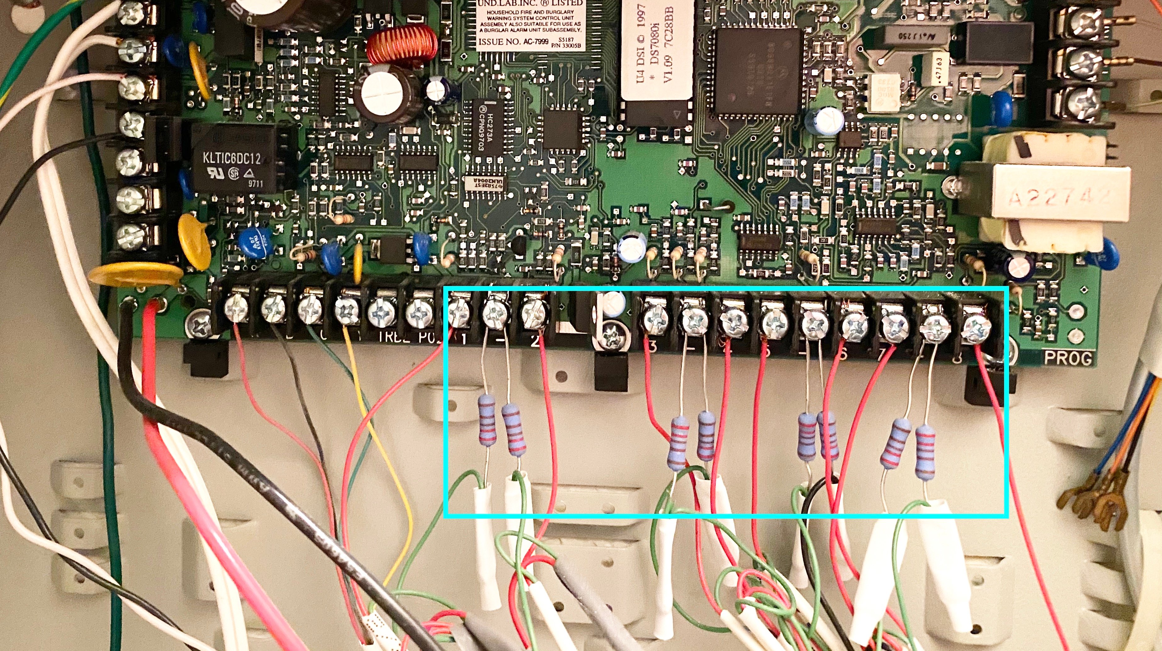
Single EOL Setup (Most Common for Panic Buttons)
- Use a NC momentary panic button.
- Place one 5.6kΩ resistor in series at the button.
- Normal state: ~5.6kΩ.
- Button press: infinite Ω (open) → alarm.
- Wire cut: infinite Ω → tamper alarm.
- Short: 0Ω → fault alarm.
Double EOL (DEOL) for Enhanced Detection
- Two resistors (e.g., 5.6kΩ series + 5.6kΩ parallel).
- Four distinct states: 0Ω (short), 5.6kΩ (secure), 11.2kΩ (alarm), infinite (cut).
- Ideal for high-risk sites where distinguishing faults is critical.
Step-by-Step: Wiring a Supervised Panic Button
- Select a quality NC momentary panic button (under-desk or footswitch type).
- Run 22 AWG 2-conductor shielded cable from the control panel zone to the button location.
- At the button, solder or crimp the 5.6kΩ EOL resistor in series with one terminal.
- Connect panel + zone wire → resistor → button NC terminal 1.
- Button NC terminal 2 → panel – zone wire.
- Secure the resistor inside the button housing or a tamper-proof junction box.
- Program the zone as “24-hour panic” or “hold-up” with tamper supervision enabled.
- Test: normal (secure), press button (alarm), cut one wire (tamper), short wires (fault).
Achieving “Cut Wire = Alarm” and Short Detection
The beauty of supervised NC loops is automatic cut detection—opening the circuit (cut) registers as infinite resistance, identical to button press in single EOL. Panels treat both as alarm events. For extra security, use DEOL to differentiate. Short detection prevents bypass: shorting wires drops resistance to 0Ω, registering as fault/tamper.
Power Loss Resilience: Keeping Panic Alive When Everything Else Dies
Panic buttons must function during blackouts. Strategies include:
- Local battery-backed siren: Wire a 12V siren directly parallel to the button (with diode isolation) so it sounds locally on activation.
- Panel battery backup: Standard in most commercial panels (up to 24–72 hours).
- Independent power supply: For extreme cases, use a dedicated UPS for the panic zone input.
Integration with Local Alarms, Remote Centers, and Dual-Path Communication
Best practice: panic activation triggers:
- Immediate local siren (audible deterrent).
- Silent remote signal to central station.
Dual-path (IP primary + cellular backup) ensures delivery even if internet fails. Modern communicators switch seamlessly.
Here are examples of integrated commercial setups:
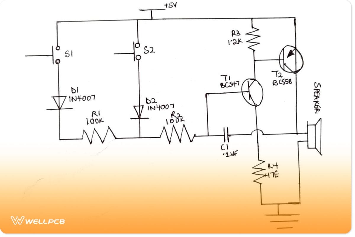
DIY Alarm Circuit Projects | PCB Design & Schematics
Scenario-Specific Wiring Strategies
Bank Teller Lines — Under-counter buttons, DEOL supervised, local silent + remote only, cellular priority (no audible escalation). Factory Floors — Multiple foot pedals in series, single EOL, loud local siren + remote. Reception Desks — Hidden button, single EOL, balanced audible/remote. Warehouses — Long cable runs, shielded cable, DEOL for cut detection.
Common Pitfalls and Advanced Tips
- Never place EOL at panel—only at end device.
- Use shielded cable in noisy environments.
- Annual resistance testing.
- Combine with wireless panic for redundancy.
In conclusion, bulletproof panic button wiring isn’t about fancy hardware—it’s disciplined, supervision-focused design that anticipates failure. Implementing these techniques turns your system from reactive to proactively secure.